Choosing a Thermal Gap Filler for AI Servers & GPUs
AI servers need a thermal gap filler that matches gap height, bond line and dispensing. Compare gap pads vs gel, six specs, and a five-step selection workflow.
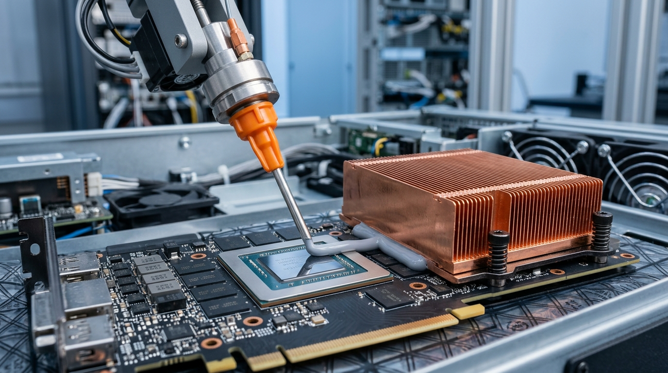
Your next AI server platform has a GPU module pulling more than 700 W, and the thermal engineer just handed you a stack of gap filler datasheets with no two specs written the same way. The choice looks like a wall of W/mK numbers, but it is really three questions: how big is the gap, how will the material be applied, and what will it do after a year of thermal cycling. Answer those in order and the thermal gap filler almost picks itself.
This guide walks through what a thermal gap filler is, when a pre-cured gap pad beats a dispensable gel, the six specs that decide performance, and a five-step selection workflow written for AI server and GPU thermal designs. It draws on manufacturer application references and standard test methods, and for the wider material family — pads, gels, phase change and their trade-offs — see our data center and AI server thermal materials guide.
What Is a Thermal Gap Filler (and Why AI Servers Need One)
A thermal gap filler is a soft, thermally conductive material placed between a heat source and a heat sink to replace the air gap that would otherwise insulate them. Thermal interface materials (TIMs) work the same way whether they are pastes, pads, gels or phase-change sheets: they conform to surface roughness and fill the space, giving heat a shorter, more conductive path out of the component. What makes a gap filler different from other TIMs is that it is built for gaps that vary — spaces between a few tenths of a millimetre and several millimetres that a thin paste layer cannot bridge.
AI servers stress gap fillers harder than most electronics, for three reasons:
- Big dies and hot spots. Accelerator packages and their HBM stacks concentrate hundreds of watts in a small footprint. The filler above the die carries heat that determines whether the part throttles, so thermal conductivity matters, but so does avoiding voids — a trapped air pocket over a hot spot can undo the benefit of a high-W/mK material.
- Component height variance. A GPU module is not flat. Die, substrate, capacitors and connectors sit at different heights, and the gap to the cold plate varies across the board. A thermal gap filler for GPU modules earns its keep by conforming to all of those heights at once with one material.
- Mechanical sensitivity. Tall components and thin substrates bend under pressure. A low-stress, soft gap filler protects them where a rigid pad or a hard-packed paste layer would not.
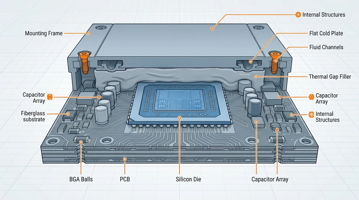
A gap filler conforms to every height in the heat path — die, BGA and passives — instead of leaving air pockets.
A thermally conductive gap filler that handles these conditions is usually a filled silicone — ceramic, alumina or boron nitride particles in a soft polymer matrix — which is why outgassing, hardness and temperature range show up on every datasheet. Those are the properties you will actually spec, and the next section decides which form of the material you need.
Gap Pad vs. Liquid Gap Filler: Two Ways to Fill the Gap
Once you know you need a gap filler material, the first fork is physical form: a pre-cured gap pad or a dispensable liquid gap filler (thermal gel). Both are sold under the "gap filler" name, and both are valid in AI servers — but they solve different problems.
A thermal gap filler pad is a cured sheet, die-cut to shape and placed between component and heat sink. It suits fixed, well-known gaps, applies with low force, and needs no curing oven or dispensing line. Manufacturers such as Laird describe gap fillers as soft, pliant materials that cover multiple heat sources in one application — that is the pad's strength: one part, one placement, several components at once.
A liquid gap filler is a paste-like gel dispensed onto the board, then either cured in place (two-component systems) or left to fill the gap under assembly pressure (one-component gels). It wins when gaps vary across the board, when the design has tall and short components mixed, or when the line already runs automated dispensing. The trade-offs are real: dispensing equipment, cure time, and messier rework.
| Factor | Pre-cured gap pad | Liquid gap filler (gel) |
|---|---|---|
| Gap range | Fixed, known gaps | Variable gaps, one material |
| Component height tolerance | Requires matched thickness | Conforms across heights |
| Assembly | Place in position | Dispense (manual or automated) |
| Curing | None (pre-cured) | One-component: cure on clamp; two-component: heat/time cure |
| Pressure on components | Low | Lowest (near-zero pressure before cure) |
| Rework | Lift and replace | Clean and re-dispense |
| Throughput | Fast, simple | Depends on dispense cycle and cure time |
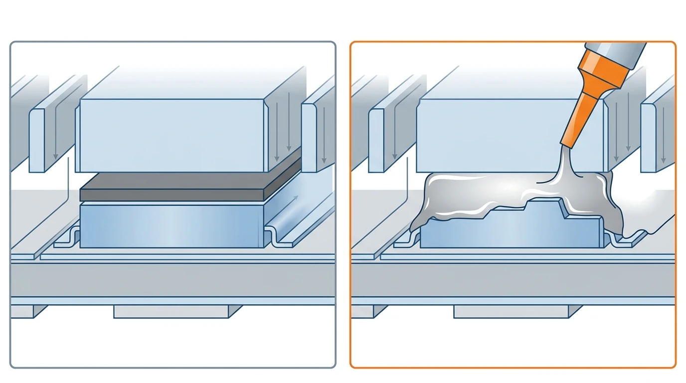
Pre-cured pads suit fixed gaps; dispensed gel fills the variable ones.
Two adjacent choices matter here too. Thermal pads and pastes are covered elsewhere on this site, and the boundary between them, gap pads and phase-change materials is worth a dedicated read — see our gap filler vs gap pad vs phase change comparison before you lock the form factor. If your gap is under about 0.5 mm and flat, a thermal pad or paste is often the simpler answer; above that, or with mixed heights, a liquid thermal gap filler or a thick gap pad earns its keep.
Six Specs That Decide a Thermal Gap Filler
Datasheets for gap fillers list a dozen numbers. Six of them decide whether the part works in your server, and the rest are context. Use these as your comparison checklist.
1. Thermal conductivity (W/mK). The headline number, but only one input. For AI server loads, 3-9 W/mK is the working range for gel-type fillers; the right value depends on the heat flux and the gap. Higher W/mK usually means a stiffer or more heavily filled material, so it is balanced against compliance.
2. Hardness and stress on components. Soft grades (low Shore OO) conform with near-zero pressure, which matters over tall, fragile components. Firmer grades hold their shape and resist squeeze-out under deep compression. Ask for the hardness value and the force it exerts at your assembly's compression.
3. Thickness and bond line control. A pad comes in a fixed thickness; a gel's bond line thickness (BLT) is whatever the assembly clamps it to. BLT control is a reliability issue: too thick adds resistance, too thin risks dry spots. The thermal pad thickness and compression guide explains the thickness-versus-compression trade in depth — the physics transfers directly to gap fillers.
4. Gap height range. Match the material's fill range to your board's gap distribution. A gel fills from tenths of a millimetre to several millimetres in one pass; a pad must be ordered to a specific thickness, so measure your gap distribution before choosing.
5. Pump-out, bleed and outgassing. Under thermal cycling, soft materials can migrate out of the gap (pump-out), bleed oil, or release low-molecular-weight volatiles that fog optics and coat contacts. Silicone-based gap fillers are the usual default, but in optical or low-outgassing zones a low-volatile or non-silicone grade may be required. This failure mode is discussed in depth for pastes, but the physics is shared — thermal paste reliability issues cover the mechanism. Most gap fillers are also electrically insulating; if you need grounding or EMI continuity instead, an electrically conductive grade is a different product family with its own trade-offs.
6. Curing and temperature range. One-component gels cure under assembly pressure at room temperature or low heat; two-component systems cure faster with a defined time/temperature schedule. Check the operating range against your board (a -45 °C to 200 °C window covers air-cooled and most liquid-cooled AI servers) and note the glass transition temperature (Tg) if the datasheet gives it — operation below Tg keeps the material compliant.
| Spec | What to check | Why it matters |
|---|---|---|
| Thermal conductivity | W/mK vs heat flux | Carries the heat that prevents throttling |
| Hardness / stress | Shore OO + force at compression | Protects tall components and thin substrates |
| Thickness / BLT | Fixed pad thickness or clamp-controlled BLT | Controls thermal resistance and dry-spot risk |
| Gap height range | Fill range vs board gap distribution | One material covering all heights |
| Pump-out / bleed / outgassing | Cycling data, volatile content | Long-term reliability, optics and contacts |
| Curing / temperature range | Cure schedule, operating range, Tg | Process fit and sustained compliance |
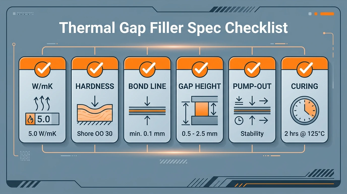
Six datasheet values separate a gap filler that survives production from one that fails after a year.
How to Match a Gap Filler to Your AI Server Thermal Design
With the specs in hand, run the selection as a sequence rather than a comparison of datasheets. This five-step workflow is the shortest path that does not skip a constraint.
Step 1 — Measure the gap distribution. Measure the air gap between the highest and lowest points in the heat path: die surface, component tops, and the cold plate or heat sink base. If heights vary more than the pad tolerance you are willing to hold, a liquid thermal gap filler is the default.
Step 2 — Set the thermal performance target. Estimate the allowable thermal resistance for the hottest component, then back out the W/mK you need at the actual bond line. The distinction between thermal resistance and thermal impedance — and which one the datasheet is quoting — trips up more than one selection, so it is worth reading our thermal resistance vs thermal impedance explainer before you compare numbers.
Step 3 — Check the mechanical constraints. List every component under the same heat sink. A filler that is comfortable for a 10 mm BGA may crush a nearby capacitor. This step decides hardness and confirms you need the low-stress class of materials.
Step 4 — Match the manufacturing process. If the line has automated dispensing, a two-component gel fits naturally. If assembly is manual or the gap is small and fixed, a pre-cut pad is faster and simpler. Also confirm cure time fits the line's takt time — a 30-minute heat cure is a process decision, not a material footnote.
Step 5 — Prototype, test, then commit. Sample the shortlist at your actual bond line, inspect for voids (X-ray or cross-section), and run thermal cycling on the assembled module, not just the material coupon. Manufacturer application pages such as Henkel's guidance on selecting a liquid gap filler underline the same point: a filler is qualified on the real assembly, because dispensing, curing and clamping all change the result.
Run these five steps and the "which gap filler is best" question answers itself — there is no universal best, only the right fit for your gap, your process and your reliability target. The same logic carries over to other high-density power electronics — EV battery packs and automotive electronics face the same gap-variance problem, and the workflow transfers with the numbers.

Measure, target, constrain, process, verify — run the five steps in order.
Reliability, Compliance and Testing to Ask For
A W/mK number is a promise; the test report is the evidence. When you qualify a thermal gap filler for AI server production, ask for documents, not adjectives.
- Thermal performance tests. Thermal resistance measured on a test method such as ASTM D5470 — the standard test method for thermal transmission of TIMs — with the bond line and pressure stated. Without the test conditions, the number cannot be compared across suppliers.
- Thermal cycling and aging data. Pump-out, bleed and conductivity drift after cycling. Ask how the material behaves after 1,000+ cycles at your operating delta-T; this is where soft fillers quietly fail.
- Flammability. UL 94 V-0 is the common gate for electronics enclosures and server components. UL's flammability testing services describe the program; a UL Yellow Card makes the rating publicly verifiable.
- Chemical compliance. RoHS and REACH declarations, and increasingly TSCA and Prop 65 for US-market exports. Our materials certification and compliance hub lists the documentation packages ZIITEK provides — a concrete example of what a complete compliance file looks like.
Specifying and Sourcing a Thermal Gap Filler
By this point the RFQ writes itself. State: the gap distribution you measured; the W/mK and thermal resistance target; hardness/stress limit; bond line or pad thickness; operating temperature range; flame rating required; outgassing limit if the application is optical or sealed; and the dispensing process (manual, automated, one- or two-component). Volume and lead time close the loop.
A concrete example of a gel-type thermal gap filler built to this checklist: ZIITEK's TIF® one-component thermal gel series spans 1.5 to 9.0 W/mK with a bond line of 0.1-0.4 mm and an operating range of -45 °C to 200 °C, UL 94 V-0 rated; the two-component AB series spans 1.5 to 5.0 W/mK for automated dispensing lines. Those are manufacturer specifications — verify them against the current datasheet when you qualify a sample, as you should with any supplier.
When you are ready to compare candidates, ZIITEK manufactures thermal gap fillers — TIF® thermal gel product range covers the dispensable grades, and the team will quote custom formulations and die-cut gap pads from drawings. Request a sample kit and specification sheet through the contact page — sample testing on your real module is the fastest way to validate bond line, voids and cycling behaviour on your own hardware.
A thermal gap filler for AI servers is chosen in the right order: measure the gap, pick the form, check six specs, match the process, and verify on the real assembly. Do that, and the datasheet wall stops being a wall — it becomes a shortlist.