EV Battery Pack Thermal Management Materials: Complete Guide
How to choose EV battery pack thermal management materials: thermal pads, gap fillers, PCMs, foams and heating films — zone by zone, with selection criteria.
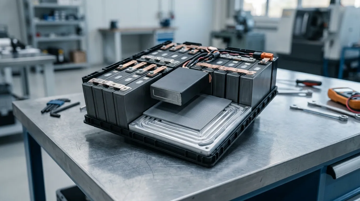
Why Battery Pack Thermal Management Depends on Materials, Not Just Cooling
Lithium-ion cells do their best work inside a narrow window. Most pack engineers target 15–40 °C during operation, with peak performance and service life clustering around 20–30 °C. Outside that band the penalties are measurable: sustained heat accelerates electrolyte decomposition and capacity fade, while cold operation slows lithium diffusion, cuts available power, and — during charging — risks lithium plating that permanently consumes capacity. At the extreme end, uncontrolled heat can cascade into thermal runaway. These relationships are well documented in the battery thermal management literature, for example in the 2024 Renewable and Sustainable Energy Reviews survey of BTMS for electric vehicles (Hwang et al., 2024).
Here is the part most system-level write-ups skip: the cooling loop only controls the bulk temperature. A liquid cold plate, immersion loop, or air stream cannot cool a cell it is not in thermal contact with. Every interface between the cell surface and the cooling medium — cell to module, module to cold plate, cold plate to coolant — is a thermal resistance, and that resistance is governed by materials. The cooling system sets the boundary condition; the materials decide whether heat actually reaches it.
This guide covers the material side of EV battery pack thermal management: which material classes exist, which zone of the pack each one serves, the specifications that matter, and how to shortlist them for a real program. For the full picture of systems and architectures, start from our EV battery thermal management materials guide, which maps the whole topic.
The Thermal Management Stack Inside an EV Battery Pack
A modern pack is not one thermal problem — it is a stack of interfaces, each with a different job. Thinking in zones makes material selection far more tractable:
Zone 1 — cell to cell. Adjacent cells exchange heat during fast charge and under imbalance. Materials here insulate more than they conduct: thin foam sheets or aerogel blankets slow lateral heat transfer and buy time against thermal propagation.
Zone 2 — cell/module to cold plate. This is the primary heat path in liquid-cooled packs. A thermal interface material (TIM) fills the air gaps between the cell or module base and the cold plate, because air at roughly 0.026 W/m·K is a terrible conductor. This zone is where thermal pads, dispensable gap fillers, and thermally conductive adhesives live.
Zone 3 — module to pack frame. Modules are bonded or clamped into the pack enclosure. Structural gap fillers and pads here conduct heat to the frame (which acts as a secondary heat sink) while damping vibration.
Zone 4 — pack enclosure. The enclosure seal is an environmental requirement with thermal side effects: foam gaskets must hold IP67/IP68 ingress protection for the life of the vehicle while surviving temperature cycling, and flame-retardant materials at the enclosure add a last line of defense.
Zone 5 — cold climate. In low-temperature operation, heating films bonded to module bases or pack walls preheat the cells before charging, preventing lithium plating.
The cell-to-pack (CTP) trend — skipping modules and placing cells directly in the pack — does not remove these zones; it compresses them. Interfaces get larger, tolerances get tighter, and the TIM between the cell and the cold plate becomes even more critical, because there is no module housing left to absorb misalignment. The same material families apply, but the required compressibility and bond-line control change.
| Zone | Thermal job | Material class | Specs that matter |
|---|---|---|---|
| Cell-to-cell | Insulate, slow propagation | Foam sheets, aerogel blankets | Conductivity ≤0.06 W/m·K, UL 94 V-0 |
| Cell/module-to-cold-plate | Conduct to coolant | Thermal pads, gap fillers, adhesives | W/m·K, thermal impedance, hardness, BLT |
| Module-to-frame | Conduct + damp | Pads, structural gap fillers | Compression set, shear strength |
| Pack enclosure | Seal, protect | Foam gaskets | IP67/IP68, compression set ≤5%, temp range |
| Cold climate | Heat the cells | Heating films | W/cm², temp range, dielectric strength |
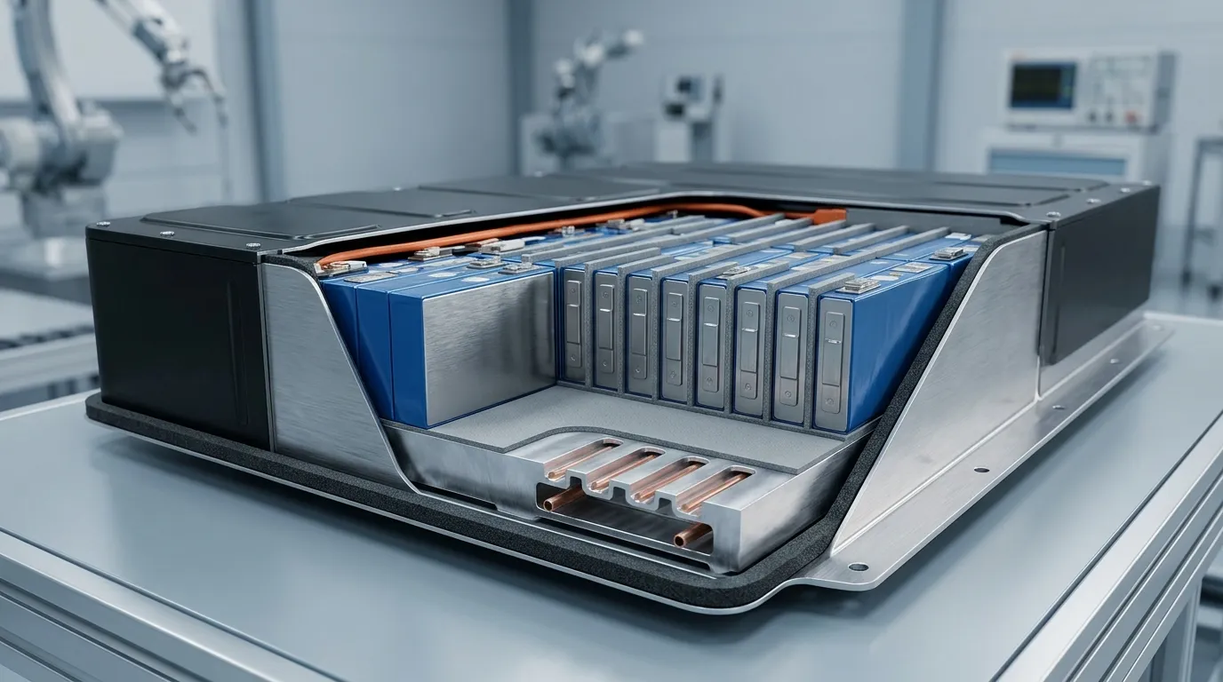
The five thermal zones of an EV battery pack: cell-to-cell insulation, cell-to-cold-plate TIM, module-to-frame, enclosure sealing, and cold-climate heating.
Thermal Interface Materials: Cell-to-Cold-Plate Heat Transfer
TIMs are the workhorses of pack thermal management. Their single job is to displace air from the interface between a heat source and a heat sink, and to hold that contact under compression, vibration, and thermal cycling. Within the pack, three form factors dominate.
Thermal pads
Thermal pads are pre-cured silicone sheets, die-cut to shape, placed between the cell/module base and the cold plate. They are the easiest TIM to design around: no cure time, no dispensing equipment, reworkable during assembly. The specifications that matter are thermal conductivity (typically 1.25–16 W/m·K in commercial grades), thickness (0.25–12 mm), hardness (Shore 00 5–70), and thermal impedance at a given pressure — softer pads conform to warped or rough surfaces at lower force, which matters when the components underneath are pressure-sensitive. Our article on how thermal pads work covers the physics; setting pad thickness against stack tolerances is a design step of its own and deserves a dedicated look before you commit to a nominal thickness.
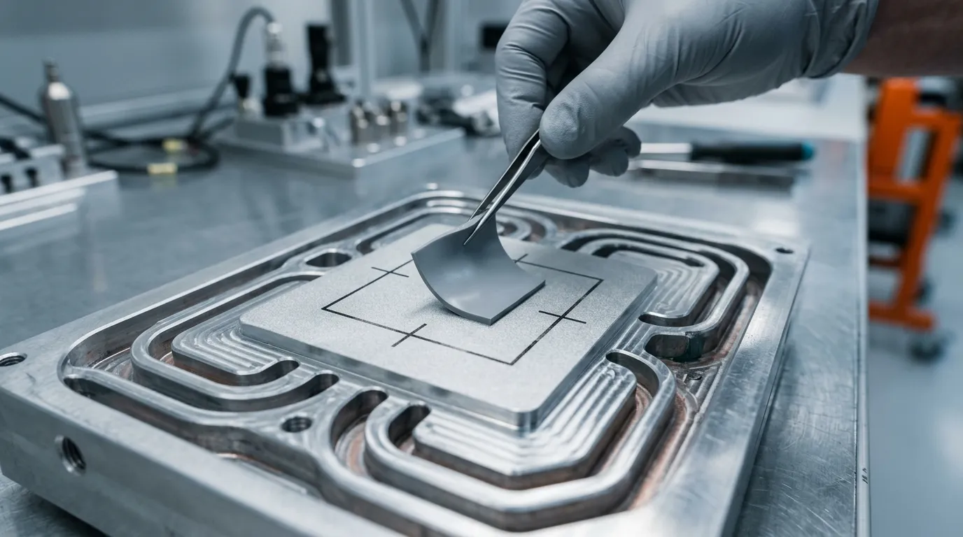
A die-cut thermal pad on the cold plate: the pad's thickness and hardness decide how well it holds contact under stack compression.
Dispensable gap fillers
Gap fillers are liquid silicones (one-part gels or two-part systems) that are dispensed onto the cold plate and cured in place. Because they start as a liquid, they conform to whatever gap actually exists — no pre-cut shape, no tolerance stack-up problem. One-part gels cure at room or elevated temperature with near-zero compressive stress, which is why they are favored over soft pads in CTP packs; two-part systems can be formulated for faster, controllable cure on automated lines.
The trade-off is manufacturing: dispensing requires a robot or semi-automated applicator, dispense-volume control, and cure time in the process flow. The payoff is lower thermal impedance at a thinner effective bond line and the ability to fill gaps of 0.5–5 mm in one pass. If you are deciding between the two form factors, our gap filler vs gap pad vs phase change comparison walks through the decision.
Thermally conductive adhesives and tapes
Adhesive TIMs bond and conduct at the same time. Thermally conductive adhesives (often epoxy or acrylic based) are used where a permanent bond is acceptable — for example, bonding busbars to the cold plate. Thermally conductive tapes (0.8–1.6 W/m·K) replace mechanical fasteners for lighter components. Both remove a part from the assembly; neither is easy to rework, so they belong where the joint will never need to open.
| Material class | Typical W/m·K | Form factor | Best for | Watch out for |
|---|---|---|---|---|
| Thermal pad | 1.25–16 | Die-cut sheet, 0.25–12 mm | Known gaps, serviceable joints, pressure-sensitive devices | Gap tolerance, hardness vs conformability |
| One-part gap filler gel | 1.5–9.0 | Dispensed, cured in place | Variable gaps, automated lines, CTP packs | Cure time, dispense control |
| Two-part gap filler | 1.5–5.0 | Dispensed AB, fast cure | High-volume automated assembly | Mix ratio, pot life |
| Conductive adhesive / tape | 0.8–4.5 | Bonded joint | Permanent joints, fastener elimination | Rework, disassembly |
| Grease | 1.0–5.2 | Screen-printed / applied film | Thin joints, maintenance scenarios | Pump-out, contamination |
One more class earns a mention: heat spreaders. Where heat must travel laterally across a cell face before it can reach the cold plate — large prismatic cells, pouch stacks — thin graphite sheets or coated foils (anisotropic, with in-plane conductivity up to ~1,700 W/m·K) spread the heat so the TIM below sees a more uniform temperature. They are usually specified as a sub-layer between the cell and the TIM rather than as a replacement for it.
One trend worth tracking: IDTechEx has documented a push among battery makers to reduce or eliminate TIMs entirely — thinner cells, more direct bonding, and structural adhesives pulling double duty (IDTechEx research article). That does not make TIM selection easier; it raises the bar. When the TIM is the only thing between the cell and the cold plate, its thermal impedance and long-term stability under compression become the whole story.
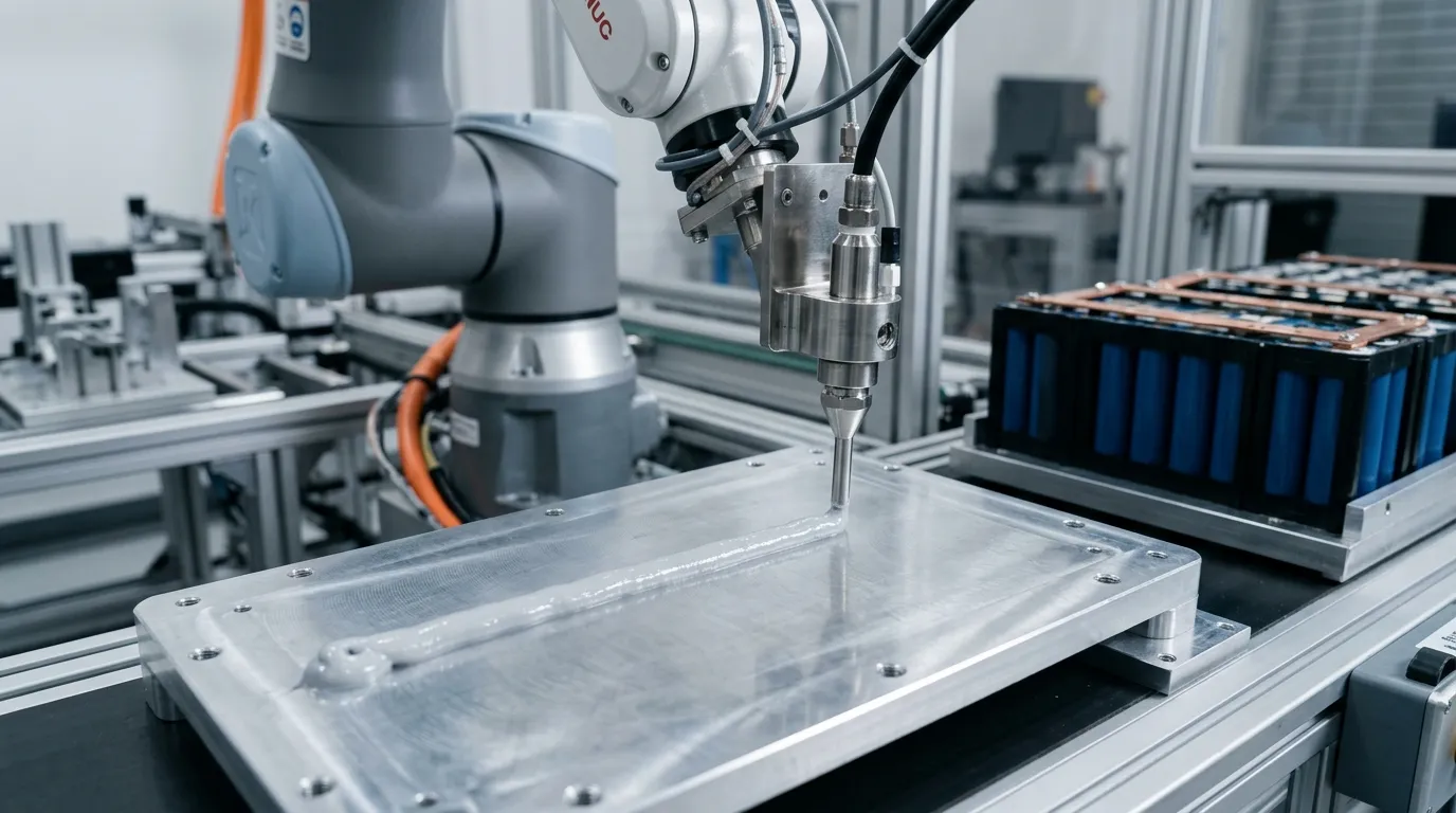
Automated dispensing of a one-part thermal gap filler onto a battery cold plate — the process that makes thin, tolerance-proof bond lines possible at scale.
Phase Change Materials: Shaving Peak Temperatures Without Added Power
Phase change materials (PCMs) absorb heat at a nearly constant temperature while they melt, then release it when they re-solidify. In a battery pack, a PCM layer next to the cells buffers short, intense heat spikes — a fast-charging burst, a high-discharge pulse — by soaking up the latent heat before the cooling loop has to handle it. Typical automotive PCM formulations melt in the 50–60 °C range and offer thermal conductivities from under 1 to nearly 10 W/m·K, with graphite- or foam-enhanced composites at the top end.
The honest limitations: a PCM has finite latent capacity, so it shaves peaks rather than removing steady-state heat; it must be paired with a cold plate or other sink to re-solidify; and it adds mass and cost. The 2024 Renewable and Sustainable Energy Reviews review of progress in battery thermal management systems surveys the active, passive, and hybrid approaches, including where PCMs actually earn their place (Gharehghani et al., 2024). In practice, PCMs make sense where the thermal load is bursty and the cooling loop is sized for average rather than peak load. Our deep dive on what phase change material (PCM) TIMs are covers the material science and the selection trade-offs.
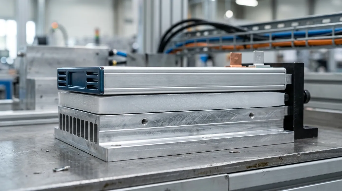
A PCM layer sits between cell and cold plate, absorbing the heat spike of a fast-charging burst before the cooling loop has to carry it.
Thermal Insulation and Fire Barriers: Containing Propagation
Not every interface in the pack should conduct heat. Between cells, the opposite is true: you want to slow lateral heat transfer so that a failing cell does not drag its neighbors into thermal runaway. This is the role of thermal insulation and fire barrier materials.
- Aerogel blankets offer the lowest thermal conductivity available (often below 0.02 W/m·K) in an ultra-thin layer, at the cost of mechanical fragility — they need protection from compression and shear during assembly and vibration.
- Silicone foams sit at the other end of the spectrum: moderate insulation (around 0.06 W/m·K) but resilient, compressible, and flame-retardant to UL 94 V-0. They double as cushioning and gap fillers between cells.
- Mica and ceramic sheets are the fire barrier. They survive well beyond the temperatures a battery fire reaches (mica withstands over 1,000 °C), provide electrical insulation, and are used at the pack level to contain propagation and protect the passenger compartment.
Propagation testing — for example, UL 2596 for thermal runaway propagation in battery enclosures — is becoming a standard gate in pack programs, and the insulation layer is the main lever engineers pull to pass it.
| Material | Thermal conductivity | Mechanical character | Role in the pack |
|---|---|---|---|
| Aerogel blanket | <0.02 W/m·K | Fragile, needs protection | Thinnest insulation between cells |
| Silicone foam | ~0.06 W/m·K | Resilient, compressible, V-0 | Insulation + cushioning + gap fill |
| Mica / ceramic sheet | Low, high-temp stable | Rigid, brittle | Fire barrier at pack level |
Foam encapsulants and thermal management materials aimed specifically at EV batteries are surveyed in detail in H.B. Fuller's white paper on thermal management solutions for EV batteries.
Sealing and Environmental Protection: The Zone People Forget
The pack enclosure has to keep water out for a decade and 200,000 km of operation, and the seal lives in the same temperature cycles as the cells. Pack sealing is usually treated as a mechanical engineering problem, but it is a materials problem with thermal consequences: a foam gasket that takes a permanent set loses its sealing force, water gets in, and the thermal system quietly degrades — to say nothing of the electrical safety risk.
The specifications that matter for a pack seal:
- Compression set — the percentage of original thickness a foam retains after prolonged compression. Low compression set (≤5%) means the seal keeps its force over the pack's life. Generic EPDM and polyurethane foams commonly exhibit 15% or higher; silicone foam formulations hold it below 5%.
- Ingress protection — IP67/IP68 ratings are the pass criteria, and the gasket is the part that makes or breaks them.
- Temperature range — the seal must survive both the cold soak (−40 °C) and the abuse cases (+200 °C class).
- Flame retardancy — UL 94 V-0 is the baseline for anything inside or at the boundary of the pack.
- Outgassing / low volatility — silicone outgassing can contaminate optical or high-voltage components; non-silicone or low-volatility grades exist for sensitive zones.
Silicone foam gaskets — for example ZIITEK's Z-FOAM®800 series, rated UL 94 V-0 and IP68 with ≤5% compression set across −40 to +200 °C — solve the sealing and thermal insulation problems in one part, which is why the one-stop thermal-plus-sealing approach is common in EV programs. The wider material family is covered in our silicone foam sealing materials guide. Elkem's overview of silicones for battery packs makes the same point from the raw-material side: the same polymer family delivers insulation, sealing, and fire protection (Elkem, thermal management materials for battery packs).
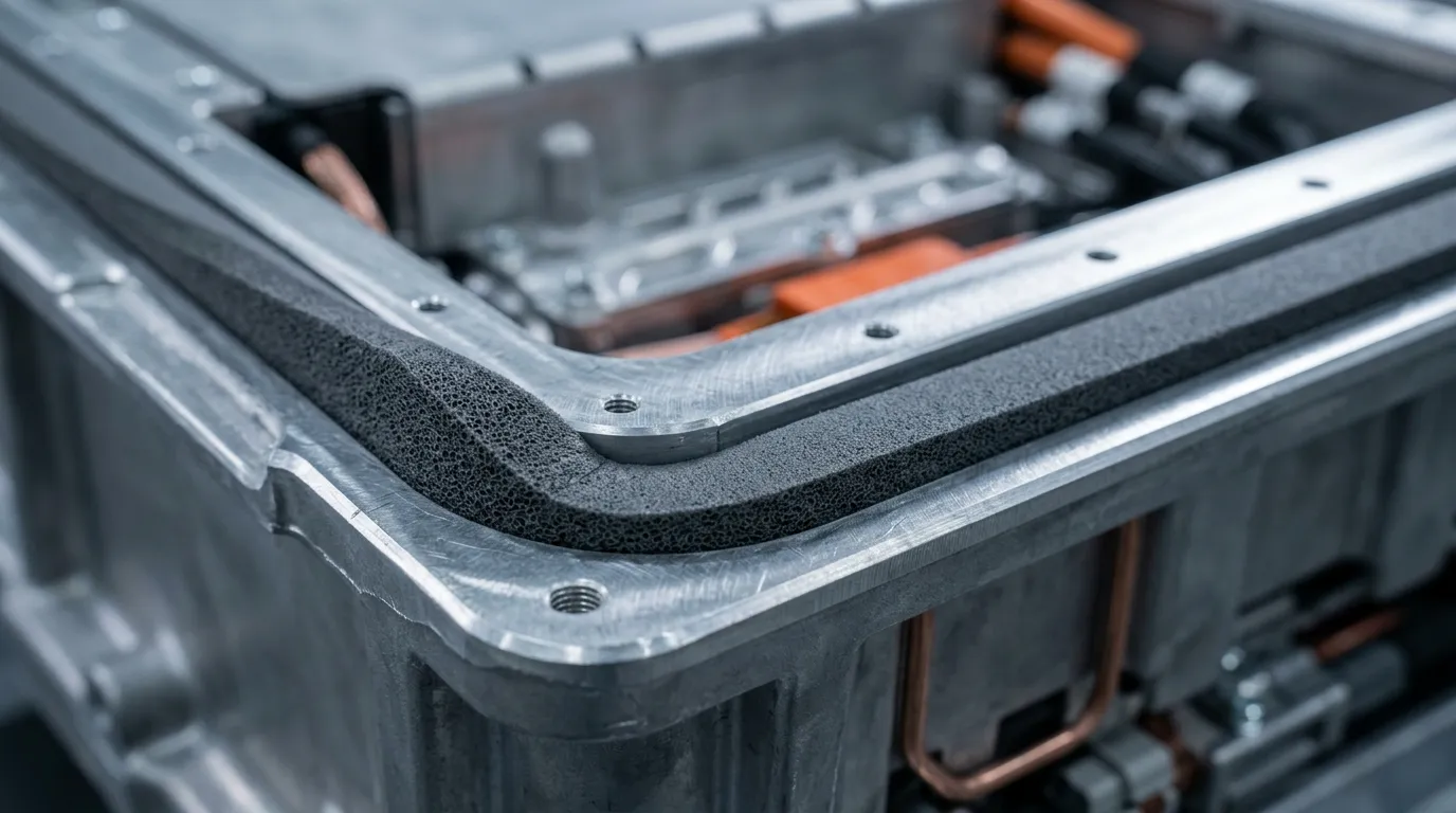
A foam gasket in the pack enclosure groove: low compression set keeps the IP68 seal alive across the pack's service life.
Cold-Climate Thermal Management: Heating Films for Low-Temperature Charging
Thermal management is not only about removing heat. In cold climates — northern Europe, Canada, northern China — a battery that is below roughly 10 °C charges slowly and riskily: lithium plating during charging permanently consumes capacity, and available power drops sharply. The industry answer is active preheating: warm the pack to a safe charging temperature before (or during) fast charging.
Heating films are the material answer. Flexible heaters bonded to module bases or pack walls deliver 1–2 W/cm² directly into the cells, with construction options that match pack requirements:
- Polyimide heating films — very thin (0.15–0.5 mm class), light, and flexible, operating from −40 to +180 °C, suited to tight, weight-sensitive integration.
- Silicone rubber heating pads — thicker and tougher, fiberglass-reinforced, operating from −40 to +200 °C, with better abrasion and moisture resistance for pack environments.
Both types are driven by AC or DC in the 1.5–380 V range, can be custom-patterned to concentrate heat where the pack needs it, and integrate temperature sensing for closed-loop control. In a pack program, the heating layer is specified together with the TIM layer beneath it: the heater sits under the module, and the thermal pad or gap filler between the heater and the cells must tolerate the heater's operating temperature over its lifetime. Heating film and heater pad design options are covered in our heating film elements guide.
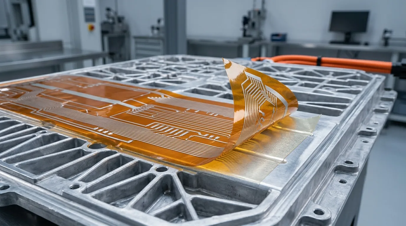
Flexible heating film on the module base — the low-temperature half of battery pack thermal management.
How to Select EV Battery Pack Thermal Management Materials: A Checklist
Selection is a sequence of decisions, not a single material pick. A workable order:
- Draw the heat path. Identify every interface from cell to coolant (or air), and assign each zone a heat-transfer job: conduct, insulate, buffer, seal, or heat.
- Set a thermal budget. Define the target thermal resistance (or maximum temperature rise) at each interface. This converts the vague goal of "keep cells cool" into numbers you can spec against.
- Choose the material class per zone. Use the table in the TIM section and the zone map above. Most packs end up with two or three TIM classes plus one insulation class plus a seal.
- Verify compliance early. Automotive-grade programs need IATF 16949-certified suppliers and materials that meet UL 94 V-0, RoHS, and REACH. A material that fails compliance at the end of a program is a redesign, not a swap.
- Design for manufacturing. Can the material be die-cut to tolerance? Dispensed on your line? Does the process flow allow cure time? A pad that must be placed by hand at 0.5 mm tolerance is a cost problem no spec sheet solves. Our how to choose a thermal interface material guide expands this decision flow.
- Test the real assembly. Vibration (LV124 class), thermal cycling, and aging (for example 125 °C / 1,000 h) expose what datasheets hide: compression set, pump-out, adhesion loss, and thermal impedance drift. Run the qualification on the actual stack-up, not on coupons.
For a worked example of this process on a real pack — a cell-to-cold-plate gap filler replacing pre-cut pads, filling 0.5–5 mm gaps at over 50% compression and passing LV124 plus 125 °C/1,000 h aging — see our new-energy vehicle battery pack thermal management case study. The industry-level view of how EV and new-energy programs are applying these materials is on our EV and new-energy industry solutions page.
Working with a Thermal Materials Partner: What to Ask
Most pack programs fail on materials not because the wrong class was chosen, but because the supplier relationship was treated as a catalog order. Before you commit, get answers to these:
- Certifications and systems. Does the supplier hold IATF 16949, ISO 9001, and ISO 14001? Are the materials UL-recognized (Yellow Card), RoHS/REACH compliant, with third-party test reports?
- Data quality. Is thermal impedance measured on ASTM D5470 equipment, at what pressure, and what bond-line thickness? B2B buyers should demand test conditions, not just a W/m·K number.
- Tolerance and converting. Can the supplier die-cut to the tolerances your stack-up needs? What is their cutting accuracy and edge quality on thin or soft materials?
- Manufacturing support. Do they support automated dispensing (for gap fillers and adhesives)? What is the shelf life and cure profile of their dispensable grades?
- Consistency and lead time. Multiple sites with identical process control matter for global programs — the material must behave the same way from every plant, every batch.
- Failure support. What happens when a material fails qualification? A partner that helps you diagnose and reformulate is worth more than one that ships samples fast.
This is the point where a one-stop supplier earns its keep: when thermal, sealing, and heating requirements are specified together, a single engineering team that controls formulation and converting across all three families removes a whole class of integration risk — which is exactly how ZIITEK structures its EV work, with in-house formulation, four manufacturing bases, and IATF 16949 certification. If you are mid-selection, ask the ZIITEK thermal engineering team for a material recommendation mapped to your pack's zone layout.
Frequently Asked Questions
What is the best thermal management material for EV batteries?
There is no single best material — the pack has different jobs in different zones. For cell-to-cold-plate heat transfer, thermal pads or dispensable gap fillers are the standard choices; for peak-temperature buffering, phase change materials; for cell-to-cell insulation and propagation containment, silicone foams and aerogels; for the enclosure, low-compression-set foam gaskets. Select per zone against a thermal budget rather than picking one "best" material.
Do EV battery packs need thermal pads?
Liquid-cooled packs need a TIM between the cells (or modules) and the cold plate, but it does not have to be a pad. Dispensable gap fillers increasingly replace pads in cell-to-pack designs because they conform to variable gaps with a thinner bond line. Air-cooled packs with low power density may skip TIMs entirely. The requirement is controlled thermal contact, and the form factor is a design choice.
What temperature should an EV battery pack be kept at?
Most lithium-ion chemistries operate safely between roughly 15 and 40 °C, with 20–30 °C as the sweet spot for performance and calendar life. Below about 10 °C, charging should be limited or preceded by preheating; sustained operation above 40 °C accelerates aging and raises thermal runaway risk.
Can phase change materials prevent thermal runaway?
No. PCMs buffer temperature spikes by absorbing latent heat, which can slow the early stages of a thermal event, but they have finite capacity and cannot stop propagation once runaway begins. Preventing propagation requires thermal insulation and fire barriers between cells, flame-retardant materials, and a battery management system that detects and isolates faults early.