EV Battery Heater: Choosing a Heating Film for Cold Preheat
How to choose an EV battery heater for cold-weather preheat: PI film vs silicone pad, power density, dielectric specs, placement, control and compliance.
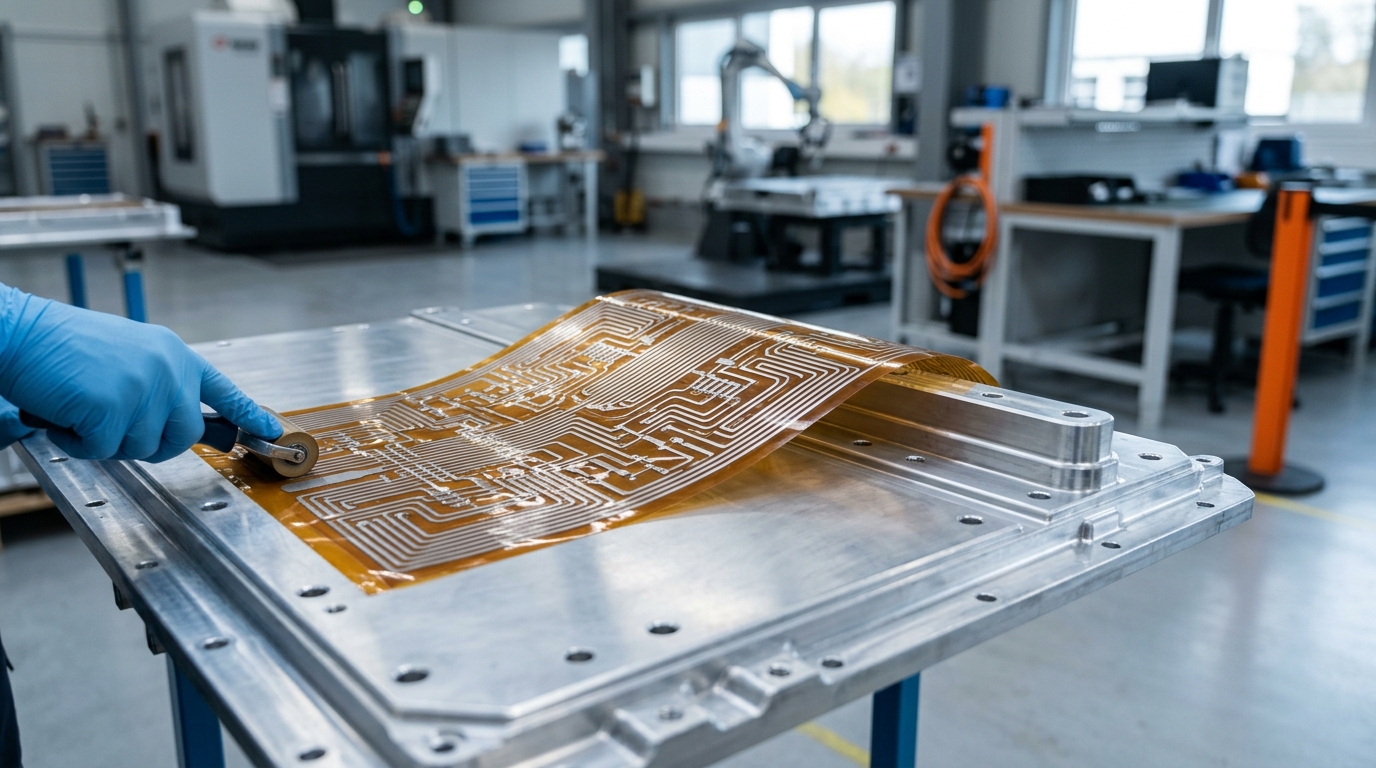
Cold Weather Turns Charging into a Battery Problem
Lithium-ion cells operate best in a narrow band — roughly 15–40 °C, with 20–30 °C as the sweet spot for performance and calendar life. Below about 10 °C, three things happen at once: available power drops, charging is throttled by the battery management system (BMS), and the chemistry itself becomes less forgiving. The 2024 Renewable and Sustainable Energy Reviews survey of battery thermal management systems for electric vehicles documents the temperature–aging relationship across cell chemistries (Hwang et al., 2024): sustained cold operation accelerates capacity fade, and the risk profile is worse than simple inconvenience.
The most serious cold-weather failure mode is lithium plating. When a lithium-ion cell is charged below roughly 0–10 °C, lithium ions can deposit as metallic lithium on the anode surface instead of intercalating into the graphite. Plated lithium permanently consumes capacity, and in the worst case grows into dendrites that can pierce the separator — a safety risk, not just a performance one. The mechanism, detection methods, and mitigation strategies are surveyed in depth in a 2021 Progress in Energy and Combustion Science review (lithium plating mechanism, detection, and mitigation in lithium-ion batteries). This is why OEM preconditioning exists: the battery is heated before charging, so that the current that flows during charging is safe for the chemistry.
The real-world cost is measurable. Recurrent's winter range study, based on fleet data from tens of thousands of EVs, found that at 32 °F (0 °C) the average EV keeps about 78% of its rated range, with the best-performing models retaining 88% and the worst only 69% (Recurrent, winter EV range loss). A share of that loss is cabin heating; a meaningful share is the battery's own reduced output and the energy spent keeping it warm.
The system-level answer — charge scheduling, preconditioning, thermal management architectures — is covered in our battery pack thermal management materials guide. This article stays on the material side: the heating element itself. If you are specifying a pack that must charge and deliver power in cold climates, you need an EV battery heater — and for most pack designs, the practical answer is a flexible heating film bonded where the heat is needed.
What an EV Battery Heater Actually Does
An EV battery heater has one job: raise the cells to a temperature where charging is safe and discharge is usable, and hold them there. Heat can be delivered three ways:
- Heated coolant. The existing liquid cooling loop is reversed or supplemented: coolant is heated (PTC or resistive heater in the loop) and pumped through the cold plates. This is how most current OEM packs do it — Hyundai's published battery warming technology, for example, heats coolant and routes it through the pack (Hyundai Motor Group). Pros: uses existing plumbing. Cons: the coolant loop heats plates, and heat must cross every interface to reach the cells.
- Cell-internal heating. Some cells (notably LFP chemistries) can self-heat by pulsing current during charge, with carefully managed protocols. No hardware added, but limited to chemistries that tolerate it and slower in deep cold.
- Attached film/pad heaters. A resistive element in a thin flexible dielectric carrier, bonded to the module base, pack floor, or between cells. Heat is generated exactly where the cells are, at 1–2 W/cm² typical, and conducted directly into the cell stack.
Film and pad heaters are the material answer, and they are how our heating film and heater pad elements guide frames the category: a flexible heater specified like any other thermal material — power density, temperature range, dielectric strength, form factor — and integrated into the pack stack.
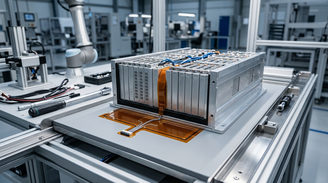
Heating film goes where the heat is needed: bonded under the module base, or placed directly between prismatic cells in the stack.
Two things worth being blunt about. First, preconditioning is a system feature: the heater is only useful if the BMS decides when to run it (typically 30–60 minutes before a scheduled charge). Second, the aftermarket products you see for consumer EVs — 12 V battery blankets, plug-in "battery warmers" — are not what a pack program needs. They are unregulated, low-power consumer accessories designed for lead-acid or auxiliary batteries, without the dielectric isolation, temperature control, or automotive compliance a lithium pack demands. They are consumer-market products, not engineering inputs.
Two Construction Families: PI Heating Film vs Silicone Rubber Pad
Flexible heaters for battery packs come in two dominant constructions, and the choice between them is mostly mechanical.
Polyimide (PI) heating films use a polyimide carrier with an etched or printed resistive circuit, sealed in another PI layer. They are extremely thin — 0.15–0.52 mm class — light (around 0.05 g/cm²), and flexible enough for small bend radii. ZIITEK's Kheat® PI heating film operates from −40 to +180 °C with dielectric strength ≥2,500 VAC, driven by AC or DC in the 1.5–380 V range.
Silicone rubber heating pads embed the same kind of resistive element in fiberglass-reinforced silicone. They are thicker (1.40–2.00 mm class), tougher, and more resistant to abrasion, moisture, and rough handling. ZIITEK's Kheat® SP silicone heating pad covers −40 to +200 °C with the same ≥2,500 VAC dielectric and 1.5–380 V drive range.
| Spec | PI heating film | Silicone rubber pad |
|---|---|---|
| Thickness | 0.15–0.52 mm | 1.40–2.00 mm |
| Operating range | −40 to +180 °C | −40 to +200 °C |
| Dielectric strength | ≥2,500 VAC | ≥2,500 VAC |
| Drive | AC/DC 1.5–380 V | AC/DC 1.5–380 V |
| Mechanical character | Ultra-thin, light, tight bend radius | Fiberglass-reinforced, abrasion/moisture resistant |
| Typical use | Between cells, thin modules, weight-sensitive zones | Module base, pack floor, vibration/rough environments |
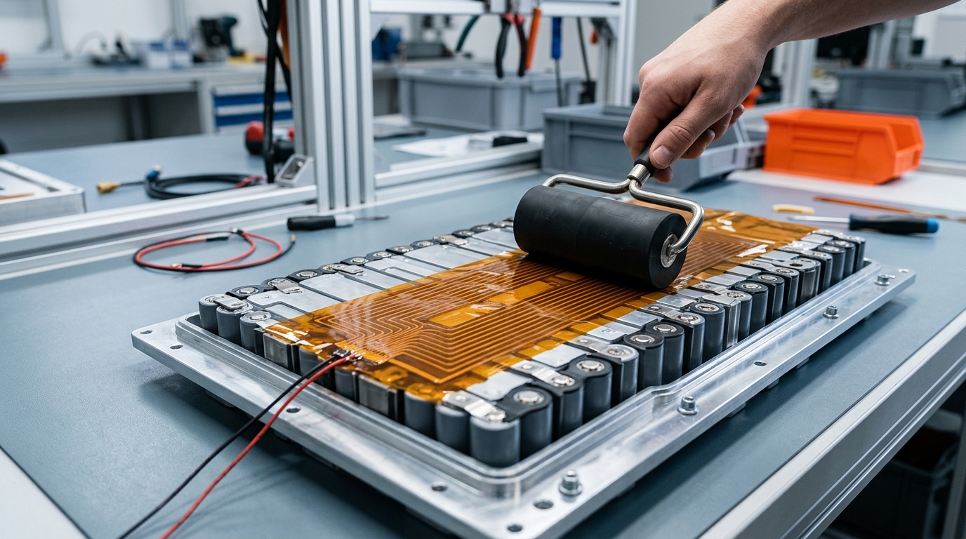
PI film: thin enough to sit between cells or under a module without changing the stack height meaningfully.
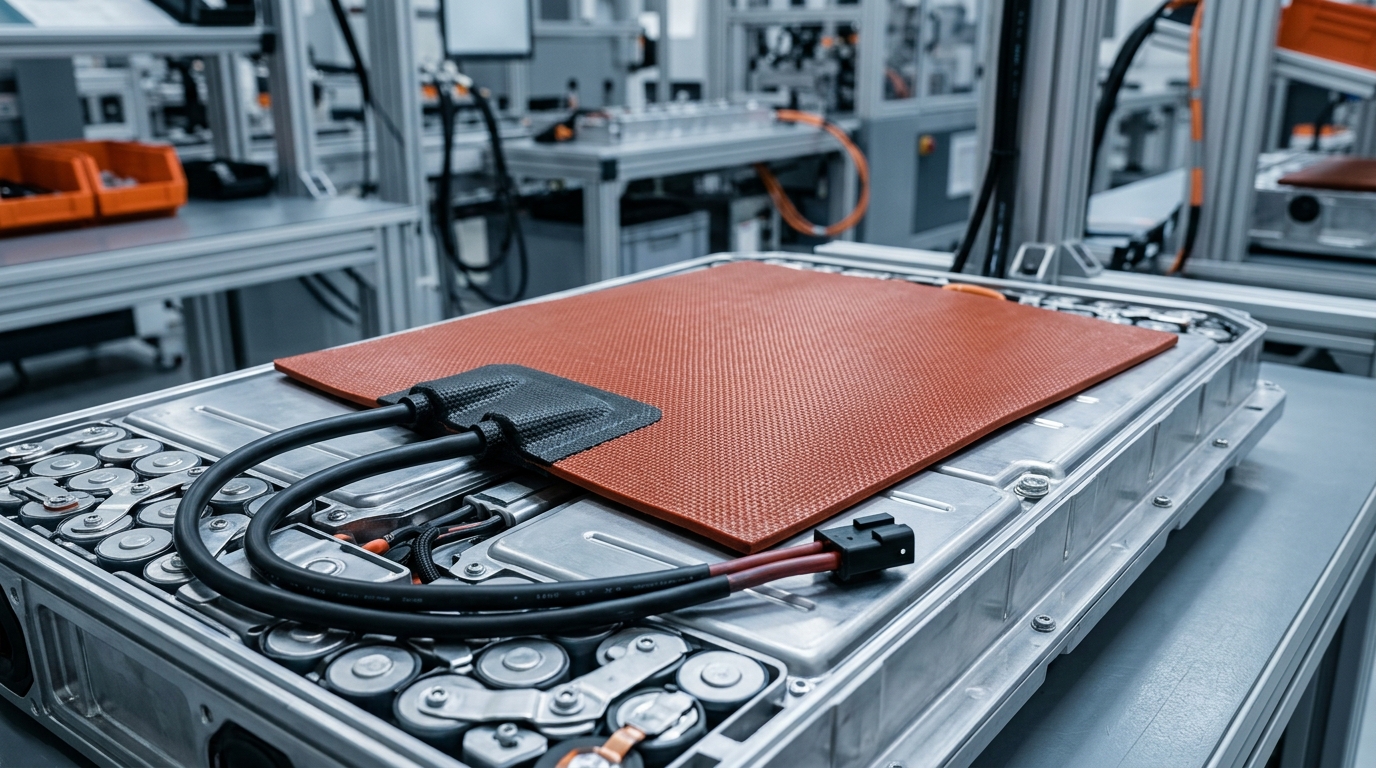
Silicone pad: more durable for pack environments where vibration, moisture, and handling dominate.
The practical rule: PI film where space and weight are the constraint; silicone pad where durability and abuse resistance are the constraint. A pack with thin prismatic cells and tight clearances will prefer film; a pack floor that sees vibration, grit, and condensation over a decade will prefer the thicker pad. Some programs use both — film between cells, pad under the module.
Sizing the Heater: Power Density, Voltage, and Dielectric Strength
A heater is specified by four numbers, and each one maps to a design decision:
Power density (W/cm²). This is how fast the pack warms. Flexible heaters in battery applications typically deliver 1–2 W/cm² — the range quoted for Kheat SP/PI films for direct integration into battery packs (EV and new-energy industry solutions). Sizing logic: total watts = active area × power density. The required watts come from a simple energy budget — cell mass × specific heat × target ΔT, divided by the desired warm-up time. Heating a 400 kg pack from −20 °C to 10 °C in 40 minutes is a different heater than keeping a pack at 5 °C overnight. Do the budget before you pick a film; a film that is undersized will run for hours, waste energy, and still not clear the charge-enable threshold.
Voltage range. The heater must match the bus it runs from — a 12 V auxiliary bus, a 48 V system, or a high-voltage pack bus with a controlled tap. Because the resistive circuit is patterned, the same physical film can be built for different voltages in the 1.5–380 V AC/DC range. Higher voltage means lower current for the same watts, which means thinner leads and less I²R loss in the wiring.
Dielectric strength. The element sits in direct contact with — or very close to — cells at pack potential. Isolation between the resistive circuit and the battery is a safety requirement, not a nice-to-have: ≥2,500 VAC dielectric strength is the standard baseline for these constructions, and it is what allows the film to be bonded directly to a module base without a separate insulation layer.
Temperature range. The heater must survive both the cold soak (−40 °C class) and the abuse cases. PI film (−40 to +180 °C) and silicone pad (−40 to +200 °C) both clear the automotive cold-soak requirement comfortably; the upper end matters if the heater can be energized when the pack is already warm.
One more spec that shows up in datasheets and deserves a skeptical look: uniformity. A film with a uniform printed pattern delivers even heat across its area; a pattern with concentrated zones delivers more where the pack needs it. If your pack has a cold corner (end modules, near the inlet), a custom pattern beats a bigger uniform film every time.
Where the Heater Goes: Placement and Stack-Up Design
Placement decides how much of the heat actually reaches the cells. Three locations are common:
- Under the module base — the most common. The heater is bonded to the module baseplate (or the pack floor), and heat conducts up through the module's own thermal path into the cells.
- Between cells — thin PI film can sit between prismatic cells or in pouch stacks, heating each cell directly. This is the most thermally efficient placement and the most demanding on thickness and reliability: the film is now part of the cell stack and must survive the full life of the pack without failure.
- On the pack wall/floor — useful for low-rate warming and for packs where modules are sealed and not to be touched.
In every placement, the heater is part of a stack-up: cells → thermal interface material (TIM) → heater → structure. The TIM between the heater and the cells does the same job it does anywhere else — displacing air, filling tolerance, and providing a low-resistance heat path. The constraint is temperature: the TIM must tolerate the heater's operating temperature over the pack's lifetime, and soft silicones that conform at low pressure are the usual choice. How the thermal interface layer works in practice — pad thickness, hardness, and pressure — applies here exactly as it does on a cold plate. The wider silicone material family — insulation foams, sealing gaskets, thermal pads — is surveyed in Elkem's overview of silicones for battery packs (Elkem, thermal management materials for battery packs).
Two engineering cautions. First, pressure-sensitive cells: the stack must not add point loads, so the heater + TIM combination should distribute force, not concentrate it. Second, bond-line tolerance: film thickness (0.15–0.52 mm) is small but not zero, and in a tolerance-sensitive stack it must be budgeted like any other layer. Adhesive-backed films simplify assembly but make rework harder — decide which matters more for your line.
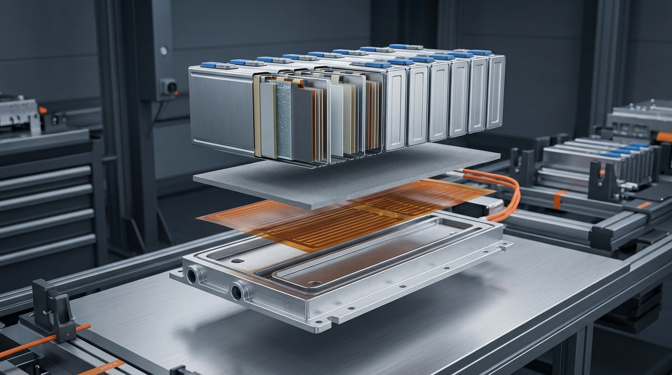
The heater is one layer in a thermal stack: the TIM above it carries heat into the cells, and the base plate below it provides mechanical support.
Closed-Loop Control: NTC Sensing and BMS Integration
A resistive heater with no control is a fire risk and an energy waste. Battery heating films are typically built with an integrated temperature sensor — an NTC thermistor or thermostat — that closes the loop. The control strategy is straightforward:
- Measure cell or module temperature (the sensor sits on the heater or on the module, placed to represent the coldest cell, not the warmest).
- Decide: below the threshold (typically 5–10 °C for charging), enable heating; above it, hold or stop.
- Target: heat to the charge-enable window (15–25 °C is a common target) rather than to maximum — heating past the window wastes energy and time.
- Coordinate with the BMS: the BMS owns the charge-enable logic and the current limits. The heater should be an actuator the BMS can command, with its own over-temperature cutoff independent of the main loop.
Edge cases matter as much as the happy path. Sensor placement: a sensor on the heater measures the heater, not the cells — if the cells are cold-soaked and the heater is bonded to a warm baseplate, the readings diverge. Condensation: rapid warm-up in a humid environment can drive condensation inside the pack; sealing and venting strategy should assume the heater runs. Deep cold: below roughly −25 °C some systems derate heating power to avoid thermal shock on cold cells. And the classic failure: a heater left on after the pack reaches temperature — which is exactly why the thermostat/NTC layer is specified as part of the heater, not bolted on later.
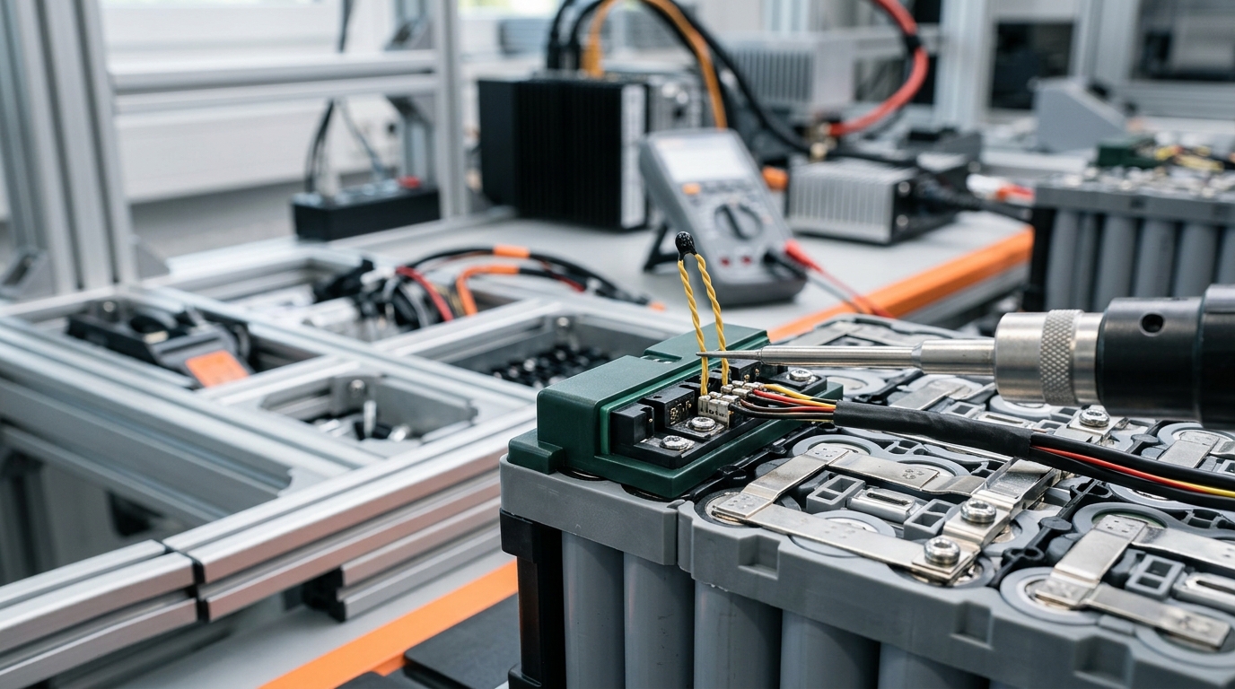
The sensor and leads are part of the heater spec, not an afterthought: closed-loop control is what makes a heating film safe to leave in the pack.
Compliance and Customization for Battery Programs
Battery programs are automotive-grade programs, and the heater must clear the same gates as every other material in the pack:
- Flammability — UL 94 V-0 is the baseline for materials inside or at the boundary of the pack.
- Electrical safety — UL recognition of the heater construction (dielectric, thermal endurance) where the OEM requires it.
- Chemical compliance — RoHS, REACH (and regional variants such as TSCA, Prop 65) for export markets; third-party test reports, not self-declarations.
- Quality systems — IATF 16949-certified suppliers are the entry ticket for Tier 1 and OEM programs; ISO 9001/14001 and QC 080000 are the supporting cast.
Do not take these on faith from a datasheet — ask for the certificate and the test report, and check the UL Yellow Card number. ZIITEK, for example, holds IATF 16949, ISO 9001, ISO 14001 and QC 080000, with UL-recognized grades under Yellow Card E331100 and third-party RoHS/REACH documentation — the kind of paper trail a battery program's materials engineer will actually be asked to produce.
Customization is where heating films stop being a commodity. A battery heater is almost never an off-the-shelf rectangle: it needs the right footprint, a patterned heat distribution (uniform across the module, or concentrated at cold corners), integrated sensors and leads, adhesive backing, and die-cut geometry that matches the module. That is a die-cutting and converting capability as much as a material question. A worked example from a real program — an EV battery pack thermal management solution designed for low-temperature environments, covering heating alongside sealing and thermal management — is documented in our low-temperature EV battery pack case study.
Specifying a Battery Heating Film: A Working Checklist
Here is the sequence we use when a pack program starts its heating design:
- Define the thermal zone and the duty. Which cells need heating, how cold does it get where the vehicle operates, and how fast must the pack reach charge-enable? Northern Europe and Canada are −30 °C design cases; most of China and the US are milder.
- Set the energy budget. Cell mass × specific heat × ΔT over the allowed warm-up time. This gives total watts; divide by the available area to get the required W/cm² and sanity-check it against the 1–2 W/cm² practical band.
- Pick the construction. PI film if thickness and weight dominate; silicone pad if durability and abuse resistance dominate. Use both if the pack has both kinds of zones.
- Fix the electrical spec. Voltage from the bus, dielectric ≥2,500 VAC, and the sensor/control requirement (NTC integrated, thermostat, or raw element for the BMS to drive).
- Design the stack. Heater + TIM + cells, with the TIM rated for the heater's operating temperature, and the tolerance budget updated for the added layer.
- Qualify on the real assembly. Cold soak, thermal cycling, vibration (LV124 class), and aging — the same gates the rest of the pack's materials go through. A heater that passes on a coupon but fails on the module is a redesign.
If you are mid-selection, the shortest path to a workable spec is a conversation with a thermal materials engineer who builds these every week — the ZIITEK engineering team can map a heating film to your pack layout, including the TIM layer beneath it and the control integration, as a single materials package.
Frequently Asked Questions
Do battery-powered heaters exist?
Yes, in two senses — and the confusion is worth untangling. There are heaters designed to run off a battery (12 V car battery warmers, heated blankets), and there are heaters designed for a battery (preheat elements inside an EV battery pack). A pack program needs the second kind: a film or pad heater driven by the vehicle's own bus, isolated to ≥2,500 VAC, with temperature control. The consumer 12 V accessories are not built to that standard.
How do you keep an EV battery warm in winter?
Three levers: preconditioning (schedule heating before charging or departure), attached heating film or pad in the pack, and insulation to slow the heat loss. OEM packs use combinations of all three; the heater itself is the active component, and insulation (silicone foam, aerogel) decides how long the heat lasts after the heater stops.
Can you add a heating film to an existing battery pack?
Retrofit is possible but not trivial. The film must reach the cells — which usually means module-level access — the stack-up and tolerance budget must absorb the added layer, and the control wiring must integrate with the existing BMS or a standalone controller with its own over-temperature cutoff. It is a design change to the pack, not an accessory install, and it should be qualified like one.
What temperature should a battery be before cold-weather charging?
Most manufacturers recommend charging above roughly 10 °C, and charge rates are typically limited below that. The practical target for a preheat system is 15–25 °C: warm enough for safe charging and good power delivery, without wasting energy heating beyond the useful window. Below about 0 °C, charging at high current is where lithium plating risk is highest.