Silicone Rubber Heater Pads: Selection Guide
How to specify a silicone rubber heater pad: watt density, voltage, temperature and thickness, plus construction, mounting, control and a supplier checklist.
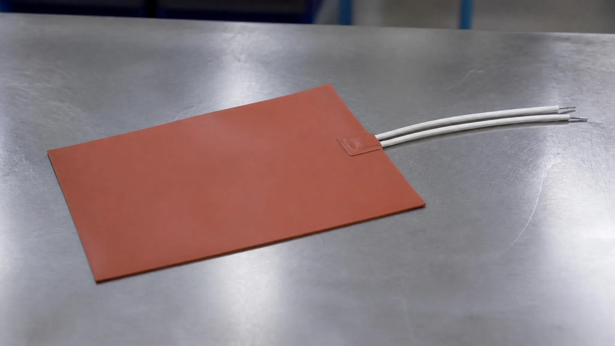
You have a surface that has to stay warm, and you have started shopping for silicone rubber heater pads. The supplier sends a catalogue: standard sizes, a wattage column, a voltage column, a note that anything else is "custom." It tells you what exists. It does not tell you what you need. The gap between "available" and "specified" is where heater projects go wrong — an undersized pad that never reaches temperature, or an oversized one that cooks the very component it was meant to protect.
This guide closes that gap. It works the way an applications engineer works: fix the four numbers that define the heater, choose a construction, decide how it attaches and how it is controlled, then verify the compliance chain. Along the way it uses one real part family as a concrete reference so the numbers stay tangible — ZIITEK's Kheat® SP silicone heating pad, which sits inside the broader heating films, heater pads and heated glass family. By the end you should have something more useful than a catalogue page: a specification you can hand to a supplier.
What a Silicone Rubber Heater Pad Actually Is
A silicone rubber heater pad is a resistive heating element laminated between layers of silicone rubber, usually reinforced with woven fiberglass for dimensional stability. The silicone does three jobs at once: it is the electrical insulator, the mechanical carrier, and — because it is thin and compliant — the thermal coupler that lets heat leave the element and reach the part with very little material in between. That last property is the whole point. A rigid heater has to heat the air and then the surface; a bonded silicone pad heats the surface directly.
The element itself comes in two constructions, and the choice shows up later in uniformity:
- Wire-wound. A fine nickel-chromium resistance wire is wound on a fiberglass core and laid into the pad. It is robust and inexpensive, and it tolerates repeated flexing, but the heat is concentrated along the wire path, so temperature uniformity is modest.
- Etched foil. A thin metal foil is chemically etched into a designed circuit and laminated between the silicone layers. Etched foil can reach higher watt densities, can be patterned for uneven heat demand, and delivers more even temperature across the pad area — at higher cost.
As a concrete reference point, the Kheat® SP silicone heating pad is a fiberglass-reinforced silicone construction rated for a 1.5–380 V drive, an operating range of −40 to +200 °C, a thickness of 1.40–2.00 mm, and a dielectric strength of ≥2,500 VAC. Those four figures — drive voltage, temperature range, thickness, dielectric strength — are exactly the kind of numbers you need for any silicone pad, and they preview the specification logic below.
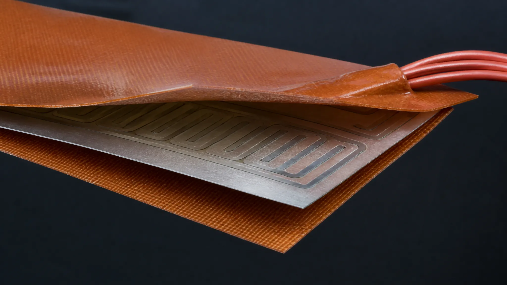
A silicone heater pad is a laminated stack: protective silicone, the resistive element, and more silicone — with a fiberglass weave providing dimensional stability.
The Four Numbers That Decide a Heater Spec
Most heater mistakes trace back to treating the pad as a component to be picked rather than a system to be sized. Four numbers do the work.
1. Power density (W/in² or W/cm²)
Power density — also called watt density — is the heater's watts divided by its active area. It sets how fast the surface warms and how hot the element runs. Because datasheets use both imperial and metric units, keep the conversion handy: 1 W/in² = 0.155 W/cm², and 1 W/cm² = 6.45 W/in². A pad quoted at 5 W/in² is about 0.78 W/cm².
The critical idea, and the one missing from every product catalogue, is that power density is an output of your thermal load, not an input you choose from a menu. Start from an energy budget:
required watts ≈ (mass × specific heat × ΔT) ÷ warm-up timepower density ≈ required watts ÷ available heater area
Heating 2 kg of aluminium (specific heat ≈ 900 J/kg·K) by 30 °C in 10 minutes needs roughly 90 W of delivered power. If your mounting area gives 200 cm², that is about 0.45 W/cm² — near 3 W/in². The same maths on a large, poorly coupled surface lands far lower, and on a small, well-sinked one far higher.
Power density is an output of your thermal load, not a number you pick off a datasheet. Size it from the heat your surface needs, then confirm that your mounting can actually carry that flux.
Manufacturers publish maximums as ceilings, not targets. Watlow, for example, lists maximum watt densities up to 12.5 W/cm² (80 W/in²) for its silicone rubber heaters, but a heater pushed to that figure assumes the heat is being removed efficiently. In practice the achievable number is set by how well the pad is bonded to its heat sink: a pad stuck to a small bracket dissipates far less than the same pad clamped to a thick aluminium plate. Choose the wattage that your heat path can carry, then confirm the surface temperature stays inside the pad's rating.
2. Voltage (and AC vs DC)
The heater has to match the bus it runs on. Low-voltage DC systems — 12 V, 24 V, 48 V — are common in battery-powered and portable equipment, vehicle auxiliaries, and outdoor electronics. Mains-driven equipment runs on 110/120 V or 220/240 V AC. For the same wattage, a higher voltage means lower current, which means thinner leads and less resistive loss in the wiring — a real advantage when the heater sits far from its supply.
Because the element is a patterned resistor, the same physical pad can be built for different voltages: the Kheat® SP range spans 1.5–380 V, which covers low-voltage DC through mains AC in one product family. Fix the voltage first, because it constrains the element pattern and the lead specification.
3. Operating temperature range (and margin)
A silicone pad's working range is broad — roughly −40 to +200 °C for the silicone construction above — but the honest question is not the range on the datasheet; it is the margin above the hottest the part will ever get, including a fault condition. A pad that normally runs at 60 °C but can be left energised with no load may see far higher surface temperatures. Size the element so its steady-state surface temperature sits comfortably below the pad's rated maximum, and add independent over-temperature protection (see control, below). Thin polyimide film heaters typically stop at a lower ceiling, around 180 °C, which is one reason a silicone pad is chosen when the duty is hot and abusive.
4. Thickness (mm)
Thickness is a stack-up budget line. Silicone pads are thick relative to film heaters — the Kheat® SP range is 1.40–2.00 mm — and that thickness buys durability, abrasion resistance, and tolerance to rough handling, at the cost of a slightly longer heat path and a taller stack. If the pad sits between two parts, that millimetre or two has to be in the mechanical tolerance budget like any other layer. Where space is the binding constraint, a thin film heater (0.15–0.52 mm class) is the alternative — see the comparison below.
| Number | What it controls | Typical silicone-pad range |
|---|---|---|
| Power density | Warm-up speed and element temperature | Set by the load; ceiling ≈ 12.5 W/cm² (80 W/in²) |
| Voltage | Element pattern and lead gauge | Low-voltage DC to mains AC; pad family 1.5–380 V |
| Operating temperature | Material choice and margin | −40 to +200 °C (silicone); ≈180 °C ceiling (PI film) |
| Thickness | Stack-up and durability | 1.40–2.00 mm (silicone); 0.15–0.52 mm (PI film) |
Silicone Rubber, Polyimide Film, or ITO Glass?
Silicone is one of three practical flexible-heating families, and the right one depends on what the application punishes most — space, temperature, abuse, or the need to see through the heater.
| Attribute | Silicone rubber pad | Polyimide (PI) film | ITO heated glass |
|---|---|---|---|
| Construction | Element laminated in fiberglass-reinforced silicone | Element laminated in thin polyimide film | Transparent conductive oxide coating on glass |
| Thickness | 1.40–2.00 mm class | 0.15–0.52 mm class | Glass panel |
| Drive | AC/DC, 1.5–380 V | AC/DC, 1.5–380 V | Low voltage, 1.5–36 V |
| Operating range | −40 to +200 °C | −40 to +180 °C | Panel-dependent; glass carrier |
| Dielectric strength | ≥2,500 VAC class | ≥2,500 VAC class | Depends on glass build |
| Best when | Durability, moisture, vibration, rough handling dominate | Space and weight are the constraint; tight bend radius | You need a heated transparent surface (windows, optics, displays) |
The decision rule is mechanical, not electrical. Choose silicone when the environment is hostile — moisture, grit, vibration, a surface that gets handled — and the extra thickness is affordable. Choose polyimide film when the stack is tight, the part is thin, or weight matters, such as heating between closely spaced cells or inside a slim module. Choose ITO glass only when the heated surface must also be optically transparent, for example a heated window or a defogging optical cover, where a film or pad would block the view. The polyimide heating film page covers that family in depth; the three constructions often coexist in one system, each doing the job the others cannot.
Mounting: Adhesive, Vulcanized Bond, or Mechanical Clamp
How the pad attaches is not an installation detail — it is a thermal decision, because the bond line is part of the heat path.
- Pressure-sensitive adhesive (PSA). A factory-applied adhesive backing makes the pad a peel-and-stick part. It is the fastest to install and needs no fixturing, but the adhesive layer adds thermal resistance, and PSA bonds are generally reserved for lower-watt-density pads where the heat flux is modest. It is also the least rework-friendly option.
- Vulcanized / factory bonding. The silicone is cured directly to the mating surface or to a metal backing plate during manufacture. This is the best thermal path and the most durable bond, and it is the right choice when the pad is a permanent part of an assembly. It costs engineering time up front, because the geometry is fixed at build.
- Mechanical clamping. The pad is held between flat metal surfaces under pressure. Clamping is used for the higher-watt-density pads precisely because it keeps the bond line and the heat path under control and lets the metal carry the flux away. The trade-off is that clamping force must be even — an uneven clamp creates the very hot spots you were trying to avoid.
| Mounting method | Best for | Trade-off |
|---|---|---|
| PSA adhesive backing | Low-watt-density pads; fastest install | Adds thermal resistance; least rework-friendly |
| Vulcanized / factory bond | Permanent assemblies; best thermal path | Geometry fixed at build |
| Mechanical clamping | High-watt-density pads | Needs even clamp force; uneven clamp makes hot spots |
A useful rule of thumb that shows up across heater manufacturers: low-wattage anti-condensation pads (tens of watts) are typically adhesive- or RTV-mounted, while high-wattage pads (tens of watts and up, densely loaded) are clamped between flat surfaces with no adhesive at all. Whatever the method, the pad is usually one layer in a thermal stack — part → interface → heater → structure — and the interface layer that fills the air gaps and carries heat into the part behaves like any other thermal interface layer. If the pad and the part are not flat, that intervening layer, not the heater, decides whether the heat arrives.
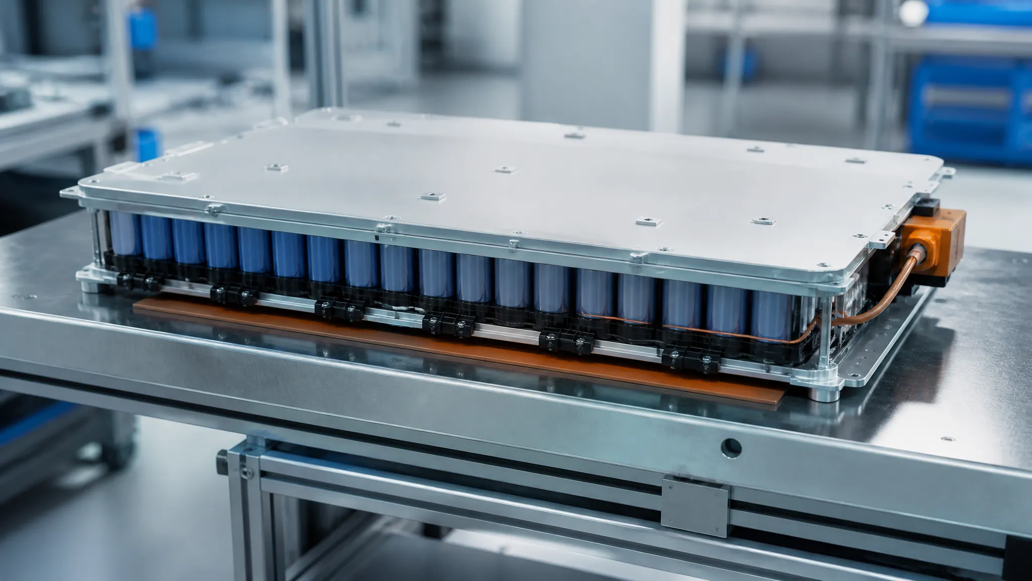
Adhesive backing for low-density pads, clamping for high-density ones — the mounting method is chosen to match how much heat the bond line must carry.
Sensing and Control: NTC, Thermostat, or PTC
A resistive heater with no control is a fire risk waiting for a sensor to fail. Flexible heaters are almost always supplied with a temperature-sensing layer, and the three options behave differently.
- NTC thermistor. A resistor whose resistance falls as temperature rises. It gives a continuous, accurate signal that a controller reads to run closed-loop control — the heater approaches a setpoint and holds it. NTC sensors are the usual choice when you want a defined temperature rather than a simple on/off limit. (The general behaviour of these devices is described in the thermistor reference.)
- Thermostat / thermal switch. A bimetallic or snap-action device that opens the circuit above a fixed temperature. It is simple, cheap, needs no controller, and is inherently fail-safe as a limit — but it only protects, it does not regulate.
- PTC (self-limiting) element. Some heater designs use a positive-temperature-coefficient material whose resistance climbs sharply with temperature, so the element throttles itself and cannot run away. PTC heaters trade a precise setpoint for a much simpler control story.
Whichever you choose, sensor placement is where controllable projects go wrong. A sensor bonded to the heater measures the heater, not the part; if the part is cold-soaked and the heater is well coupled to a warm frame, the two temperatures diverge and the control loop chases the wrong number. Place the sensor to represent the coldest point you care about, keep an independent over-temperature cutoff separate from the main control loop, and design the control so the heater cannot be left energised with the part removed. Closed-loop regulation is what makes a silicone pad safe to leave bonded inside a product.
Uniformity, Hot Spots and Watt-Density Limits
Two heaters with identical wattage can deliver very different results depending on how evenly they spread the heat.
A uniform circuit delivers even temperature across the pad; a patterned etched-foil circuit can deliberately concentrate power where heat loss is greater — the cold corner of a module, the end near an inlet, the edge that radiates to open air. This matters because every pad loses heat at its edges, so an unmanaged edge runs cooler than its centre. Etched-foil profiling is the lever that compensates: an area of the circuit with a narrower trace produces more watts per unit area and can offset a known loss.
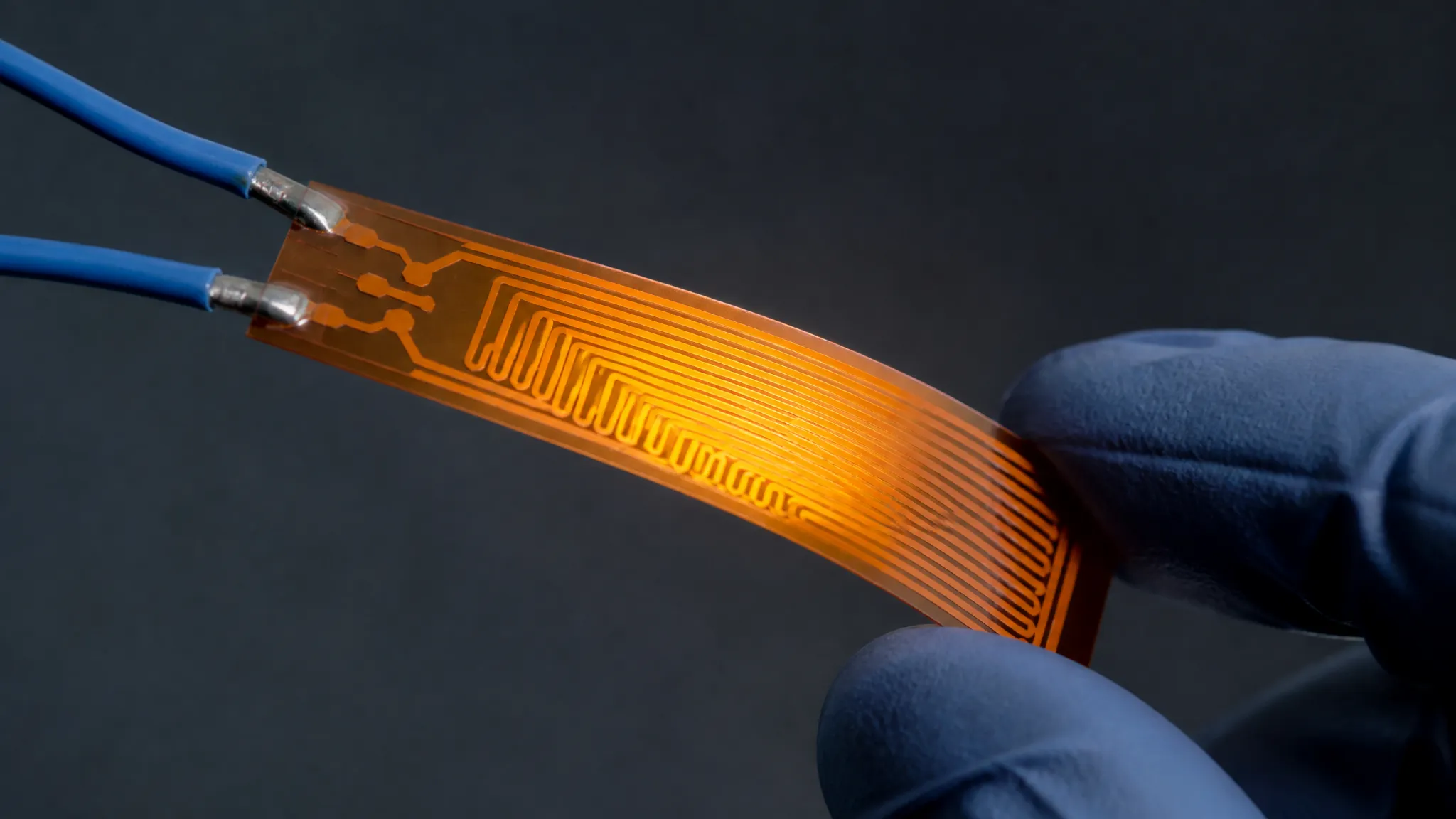
A profiled etched-foil circuit trades a uniform pattern for one that puts more watts where the surface loses heat fastest.
The limit on all of this is watt density again, now from the other direction. Push power density too high over too small an area and the local temperature climbs faster than the surrounding material can carry it away — a hot spot. Over time, hot spots age the silicone, degrade the adhesive or bond line, and shorten the heater's life. Uniformity is not cosmetic; it is the difference between reaching an even temperature and quietly cooking one small region. If your application has an unavoidable cold zone, ask for a profiled pattern rather than a larger uniform pad — a bigger uniform heater spreads the same watts over more area and may reach temperature nowhere.
Where Silicone Rubber Heater Pads Earn Their Keep
The same construction that makes these pads durable makes them the default in a handful of recurring use cases.
- Battery preheat. Cold lithium-ion cells accept charge slowly and, below roughly 0 °C, risk lithium plating. A bonded pad warms the module before charging so current can flow safely. This is the same logic that drives battery heating film selection — for the construction and placement detail on that job, see the EV battery heater selection guide, which pairs the heater with the wider battery pack thermal management system.
- Outdoor enclosures: anti-condensation and freeze protection. A small pad inside a cabinet keeps the internal surface a few degrees above dew point, so moisture stops condensing on the electronics — and keeps the enclosure above freezing in winter. This is a low-wattage, adhesive-mounted job, and it is where the IP rating of the assembly matters as much as the heater.
- Medical and laboratory equipment. Analyzers, sample lines, incubators, and reagent warmers need gentle, even heat with tight control. Here the NTC-plus-controller configuration is standard, and dielectric safety is non-negotiable.
- 3D-printer build plates. A silicone pad under an aluminium build plate is a common, cost-effective heat-bed solution: large area, moderate watt density, and enough thickness to survive the plate being removed and refitted.
- Optical-module and sensor temperature control. Optical transceivers and precision sensors drift when cold; a small pad holds them near their optimal temperature. When the heated surface must stay transparent, this is the case that pushes you toward ITO glass instead of a silicone pad.
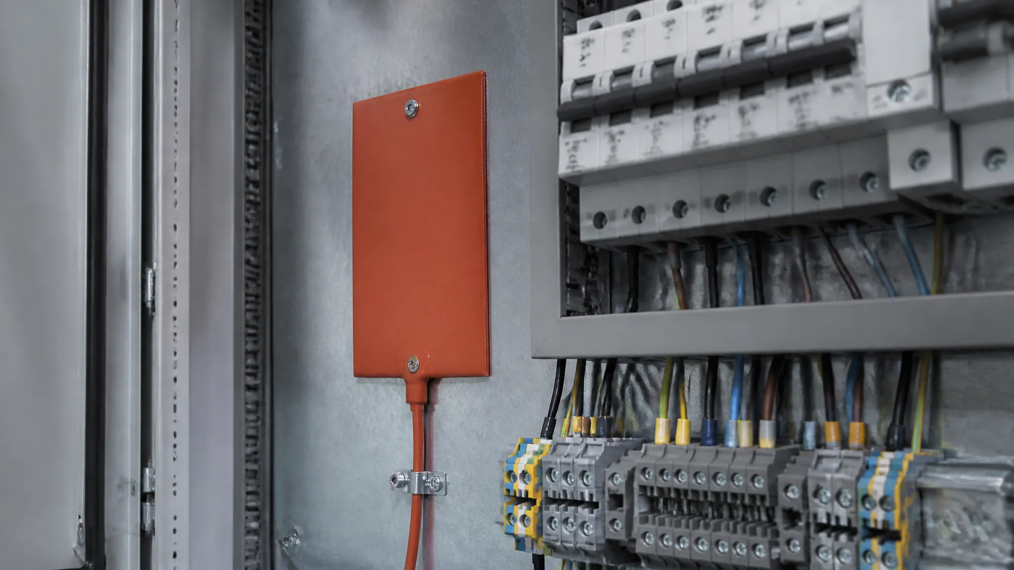
In enclosures, the job is to hold the inside surface just above the dew point — a low-wattage, adhesive-mounted pad does it well.
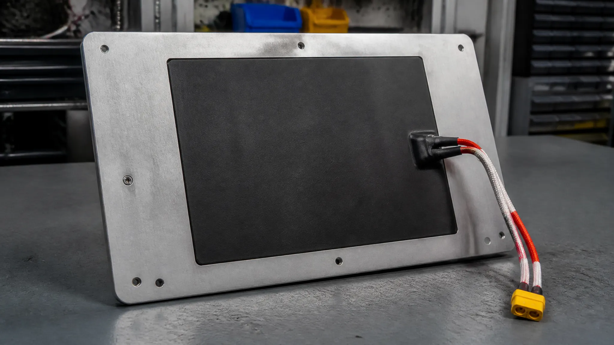
Under a printer's build plate, a wide pad at moderate watt density spreads an even bed temperature.
Compliance and Insulation: What to Demand, Not Assume
Inside a heater, the element sits at a potential and the user's hand, housing, or battery sits millimetres away. The insulation is the safety case, so treat the compliance chain as a set of documents to verify, not adjectives on a sales page.
- Dielectric strength. The isolation between the element and the outside world. A silicone pad in this class is specified at ≥2,500 VAC, which is what lets it be bonded directly to a metal surface without a separate insulating layer. Ask for the tested value on your part, not the family range.
- Flammability. Materials inside or at the boundary of electrical equipment are usually required to meet a flame rating such as UL 94 V-0. The rating is specific to the tested specimen and thickness, so confirm which grade was tested at which gauge (UL Solutions' overview of its combustion tests and the UL 94 reference explain what the rating does and does not prove).
- UL recognition (the file, not the claim). A genuine rating sits on a UL file, and plastics and rubbers are covered by a "yellow card" that lists the grades and thicknesses actually tested (how to read a UL yellow card). Be precise about scope: ZIITEK's UL Yellow Card E331100 covers specific material grades — not the heater construction itself — so a heater part's UL recognition is a separate document to request. Do not let a material-level credential stand in for a part-level one.
- Chemical compliance. For export, the documents that matter are RoHS (restricted substances in electrical equipment, per the EU RoHS directive) and REACH (chemical registration and SVHC obligations, per the EU REACH regulation), usually supported by third-party reports for SVHC, TSCA, POPs, PAHS, PFAS and California Prop 65.
- Quality systems. Automotive and battery programs gate suppliers on IATF 16949; ISO 9001, ISO 14001 and QC 080000 (hazardous-substance process management) are the supporting systems. ZIITEK holds all four, and the point is not the badges — it is that a battery program's materials engineer will ask for the certificates and the test reports, so have them ready to produce.
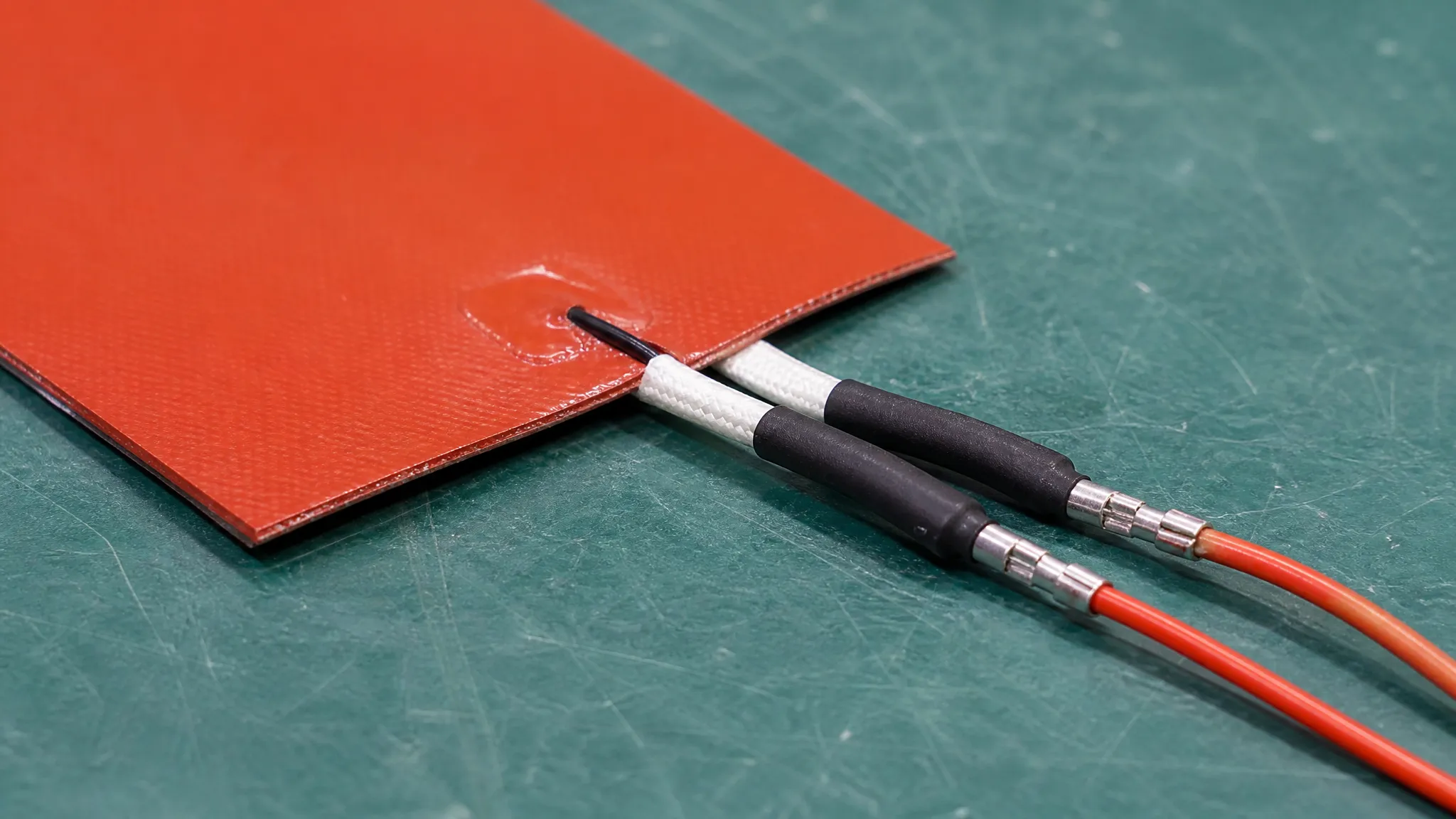
The sensor and termination are part of the heater specification: closed-loop control and a documented insulation value are what make the pad safe to leave installed.
Silicone Rubber Heater Pad Selection Checklist
Work through this in order; each step narrows the next.
- Define the load and the duty. What is being heated, its mass and specific heat, the target ΔT, and the warm-up time allowed. This produces the required watts.
- Compute the power density. Required watts ÷ available area, converted to your preferred unit (1 W/in² = 0.155 W/cm²). Sanity-check it against what your mounting can carry.
- Fix the voltage. Low-voltage DC (12/24/48 V) or mains AC (110/220/240 V). Match the element pattern and lead gauge to the bus.
- Set the temperature range and margin. Steady-state surface temperature, plus any fault condition, must sit inside the pad's rating with headroom.
- Choose the construction. Silicone for durability and abuse; polyimide film for thin, tight stacks; ITO glass only when the surface must be transparent.
- Choose the mounting method. Adhesive/RTV for low watt density; clamped or vulcanized for high watt density or permanent assemblies.
- Specify sensing and control. NTC for regulation, thermostat for a limit, PTC for self-limiting simplicity — plus an independent over-temperature cutoff.
- Plan uniformity. Uniform pattern by default; a profiled etched-foil pattern where cold zones are known.
- Confirm the compliance documents. Dielectric value, flame rating, UL file (part-level), RoHS/REACH reports, and the relevant quality-system certificates.
- Define the physical part. Outline, cut-outs, lead length and termination, adhesive or backing, and the tolerance that keeps the stack from over-compressing the heater.
Frequently Asked Questions
What is the difference between a silicone heater pad and a silicone heating film?
They are the same idea in different carriers. A silicone rubber pad encapsulates the element in fiberglass-reinforced silicone, so it is thicker and tougher; a polyimide film heater uses a thin film carrier, so it is much slimmer and lighter but less resistant to abrasion and handling. Choose the pad for hostile environments and the film for tight, weight-sensitive stacks.
Can I run a silicone heater pad on 12 V or 24 V DC?
Yes. Low-voltage DC is common for battery-powered and vehicle-auxiliary equipment, and a single product family can span the range — the Kheat® SP line, for instance, is built for 1.5–380 V, which covers 12/24/48 V DC and mains AC. The constraint is current: at a fixed wattage, lower voltage means higher current and thicker leads.
How do I know what watt density to specify?
Work backwards from the load, not forwards from a catalogue. Estimate the watts needed from mass × specific heat × ΔT ÷ time, divide by the area you can cover, and treat the result as a requirement to match against your mounting's heat-transfer capacity. Manufacturer maximums (Watlow lists up to 12.5 W/cm² for silicone rubber heaters) are ceilings for well-sinked designs, not everyday targets.
Why do some heater pads use adhesive and others are clamped?
Adhesive and RTV mounting suits lower-watt-density pads, where the modest heat flux can cross the adhesive layer without overheating it. Higher-watt-density pads are clamped between flat metal surfaces so the heat is carried away through the metal and the bond line is not asked to do work it cannot survive. The mounting choice follows the watt density.
Is a silicone rubber heater pad safe to leave installed and powered?
Only with control. A heater needs a sensing layer — an NTC for regulation, or a thermostat as a limit — and ideally an independent over-temperature cutoff outside the main control loop. Combined with a verified dielectric strength (≥2,500 VAC in this class), that control layer is what makes the pad safe to bond permanently inside a product.
Silicone rubber heater pads are not hard to specify once you replace "which size?" with four numbers, a construction choice, a mounting decision, and a control layer. Pick the watt density from the load, match the voltage to the bus, leave temperature margin, and budget the thickness in the stack — then make the supplier prove the insulation and compliance rather than assert them. When you have a load and a footprint in mind, ZIITEK's applications engineers can turn that into a specified pad — element pattern, leads, sensing and attachment — as a single thermal package.