KHEAT-PI Polyimide Heater on a Thermal Test Vehicle
By Ziitek Electronics · Published
A thermal-validation laboratory needed a thin heat-source component that could bond directly to a copper thermal test vehicle, or TTV. Ziitek's client brief describes selecting a KHEAT-PI etched-foil heater film for that position in the fixture. This TTV polyimide heater case study follows the component arrangement, electrical and mounting inputs, and the validation records needed to interpret the reported integration.
A laboratory needed a heater bonded directly to its copper TTV
A thermal-validation laboratory needed a thin heat-source component that could bond directly to a copper thermal test vehicle, or TTV. Ziitek's client brief describes selecting a KHEAT-PI etched-foil heater film for that position in the fixture. This TTV polyimide heater case study follows the component arrangement, electrical and mounting inputs, and the validation records needed to interpret the reported integration.
The anonymous customer is a thermal-validation laboratory and semiconductor test house in China, serving server manufacturers, chip designers and thermal-module teams. The fixture was intended to support evaluation of heat sinks, thermal pads and cold plates before production decisions.
The source describes an earlier ceramic heater block plus mica-sheet arrangement. For that laboratory's setup, the reported difficulties were mechanical bulk, inconsistent contact, temperature differences around the resistance-wire layout, changing heat-load requirements and electrical-insulation concerns during extended runs. Those are the customer's stated reasons to review the configuration, not universal findings about every ceramic or mica heater.
The existing polyimide heater specification guide for TTV fixtures covers the general design inputs. This case adds the specific copper-surface arrangement and the introduction sequence described in the client material.
The foil pattern and bond stack formed one heat source
The selected KHEAT-PI polyimide heater uses a PI-film and etched-foil construction. In the described application it bonds directly to the copper TTV surface, replacing the earlier heater stack. Heater geometry and attachment therefore became part of the heat-source configuration rather than separate afterthoughts.
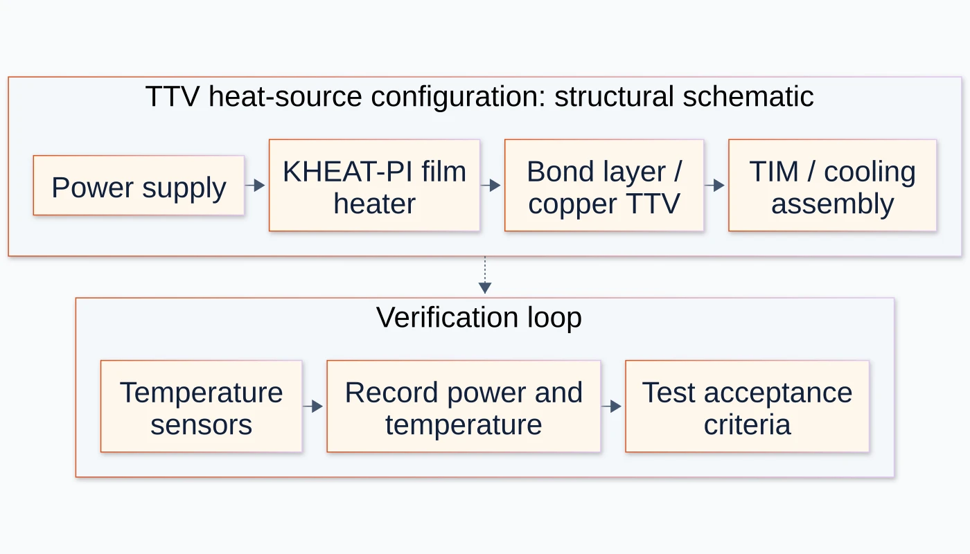
The cover schematic shows the relationship between electrical input, film heater, bond layer, copper surface and cooling assembly under test. The sensor/recording branch represents a verification requirement. It is not a photograph of the customer's fixture or a measured temperature field.
The table records the configuration range in the client-confirmed visible PPT. It does not specify that a single manufactured heater accepts every voltage, thickness and power level in the range.
Configuration input | Source-listed value or construction |
|---|---|
Heater construction | PI film with etched foil |
Thickness options | 0.1–0.52 mm |
Family supply options | 1–220 V AC/DC; the actual design voltage must be specified |
Recommended power density | 0.1–0.6 W/cm² |
Operating-temperature range | −40 to 130 °C for the confirmed configuration |
Dielectric withstand | ≥1000 VAC for one minute, as a source test entry |
The client's temperature confirmation resolves the older source discrepancy for this published configuration. Film, adhesive, leads, substrate and control settings still need to be identified for the actual part. The older downloadable product PDF should not be used to introduce a different temperature limit into this case.
Electrical power had to be tied to the heated area
The heat source had to be specified for the laboratory's test task. An outline drawing alone would not establish the active heated area, nor would a family voltage range identify the resistance and electrical power of the selected foil pattern.
The project brief presents recommended power density of 0.1–0.6 W/cm². The specification review must connect that value to the actual active area and electrical input, then check the resulting operating temperature after attachment to the copper surface and cooling stack. Actual active-area dimensions, resistance and selected voltage are not included in the supplied project record, so a unique wattage cannot be reconstructed from it.
A uniform source target and a spatially varying chip power map are also different validation tasks. This application describes a bonded heater component; it does not establish a multizone TTV platform, on-die sensing or reproduction of a particular semiconductor's hotspot map. The test objective should determine which temperature-distribution criterion is required.
For other constructions, the film heating element range is the selection entry point. The case does not prescribe this PI construction for every thermal-test fixture.
Bench integration and uniformity needed separate records
The presentation's validation table describes bonding to the TTV and test-bench readiness alongside material/configuration entries. It does not supply a calibrated surface-temperature map or a measured uniformity tolerance.
Verification question | What is in the source | Record needed for a new fixture |
|---|---|---|
Was a thin heater configuration identified? | PI/etched foil, thickness and electrical family options are listed | Part drawing, active area, resistance and selected supply |
How was it attached? | Direct bonding to the copper TTV surface is described | Substrate preparation, attachment construction and bond/contact inspection |
What thermal field was achieved? | Uniform heating is a project target; no numeric spread is supplied | Sensor positions, calibration, ambient/cooling conditions, power and steady-state criterion |
What electrical check is listed? | ≥1000 VAC for one minute is a source withstand entry | Applicable test setup, acceptance criteria and the selected assembly's test record |
What establishes repeatability or life? | Uniformity/power and insulation/life stages are named | Repeated-run data, test duration, failure criteria and controlled fixture conditions |
A published thermal-validation experiment provides useful external method context: it describes its own film-source/copper test arrangement and operating boundaries. Its measurements belong to that different setup and are not evidence for KHEAT-PI performance.
For this customer reference, the publishable result is the described thin bonded heat-source configuration and its reported bench integration. There is no numeric claim for temperature spread, hotspot elimination, faster testing or energy saving. A simulated image or a decorative curve would not supply those missing measurements.
The electrical withstand entry is a test condition, not an operating-voltage instruction or a finished-machine safety approval. A laboratory should qualify the selected supply, wiring, sensing and control arrangements for its own equipment.
The source describes an approximately nine-week introduction
The presentation gives a project sequence of two weeks for the custom sample/prototype, one week for TTV bonding, two weeks for uniformity/power testing and four weeks for insulation/life testing. It describes production release at approximately nine weeks in total.
This is the source's introduction sequence, not a current delivery guarantee. The record does not identify procurement, queueing, retest or approval assumptions that would let another laboratory reproduce the calendar directly. For a new fixture, agree on the drawing, test protocol and acceptance milestones before treating an introduction estimate as a schedule.
What another validation laboratory should specify
Three lessons transfer to a similar review: specify the heater together with the copper/bond stack; connect power density to a defined active area and electrical design; and separate a target for uniform heating from the measurements that would demonstrate it.
Prepare the TTV outline, copper/substrate description, active area, cutouts and lead-exit requirements. State the selected voltage and desired electrical power, attachment method, cooling conditions, sensor locations, controller behavior and temperature-distribution criterion. Identify whether the intended test is steady-state or transient, and which assembly or interface is being evaluated.
Request a KHEAT-PI TTV configuration review with those inputs. The existing polyimide heating film design article provides wider application context; the grade-specific product page remains the place to review the available component construction.
Source: client-supplied Kheat PI Heater Film · TTV Chip Heat Source · Thermal Test Validation Case, reviewed 30 October 2026, especially slides 3–8. The customer's identity remains anonymous. Configuration values follow the confirmed visible PPT; no simulation temperature scale or unprovided thermal-imaging result is presented as measured project evidence.
Related thermal-management references
Frequently asked questions
What did KHEAT-PI replace in the described TTV arrangement?
The client brief describes a PI/etched-foil heater bonded to the copper TTV surface in place of an earlier ceramic heater block plus mica-sheet arrangement. It is a heat-source component configuration, not a complete semiconductor test platform.
What operating-temperature range applies to this case?
The client-confirmed visible PPT specifies −40 to 130 °C for the published configuration. The actual film, attachment, substrate and control conditions still need to be identified for qualification; older notes or simulation-image scales are not additional ratings.
Does the case prove a particular surface-temperature uniformity?
No numeric surface-temperature spread or calibrated heat map is supplied. Uniform heating is a project target. A new fixture needs recorded power, sensor locations, boundary conditions and acceptance criteria to establish the achieved temperature distribution.
Can one KHEAT-PI heater use every voltage in the family range?
The 1–220 V AC/DC entry describes family design options. Specify the actual voltage, resistance, active area and required power for the selected heater. It does not mean one manufactured film is interchangeable across the whole range.