TIS680-12AB Silicone Potting for a UAV ESC
By Ziitek Electronics · Published
An industrial UAV manufacturer needed its electronic speed controller to handle MOSFET heat while protecting the power board against vibration and outdoor exposure. Ziitek's application brief describes a full-board TIS680-12AB silicone potting arrangement that connected the devices and PCB to the aluminum housing. This UAV ESC silicone potting case study explains the selected configuration, its process inputs and the distinction between material specifications and the reported assembly checks.
A 30–60 A ESC had to dissipate heat and protect the board
An industrial UAV manufacturer needed its electronic speed controller to handle MOSFET heat while protecting the power board against vibration and outdoor exposure. Ziitek's application brief describes a full-board TIS680-12AB silicone potting arrangement that connected the devices and PCB to the aluminum housing. This UAV ESC silicone potting case study explains the selected configuration, its process inputs and the distinction between material specifications and the reported assembly checks.
The anonymous manufacturer builds multirotor aircraft for inspection, agricultural spraying and mapping. The brief describes continuous current of 30–60 A per ESC, with switching losses concentrated in the MOSFET power stage. Rain, condensation, low-temperature operation and mechanical vibration were part of the application requirement.
The original arrangement combined rigid epoxy potting with conformal coating. In this project, the customer reported stress-related board damage, inadequate heat transfer across air gaps, moisture-related leakage and difficult repair. Those observations explain the change under consideration; they do not establish that every epoxy or coating system will fail in another ESC.
For the general protection-choice discussion, see the existing conformal coating versus potting guide for drone ESCs. The focus here is the configuration described in the customer brief.
The compound connected the power board to the aluminum housing
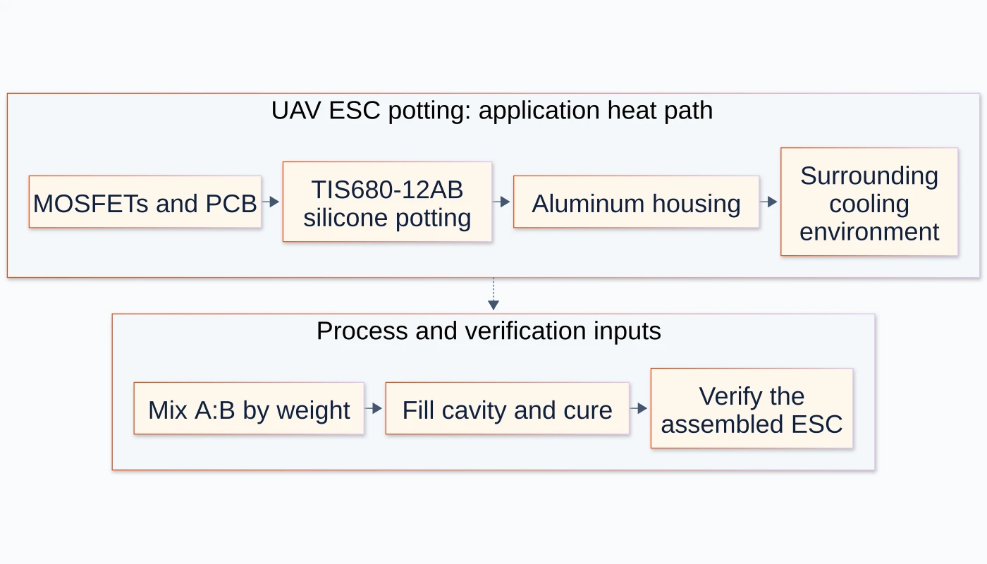
The selected TIS680-12AB silicone potting compound filled the ESC cavity around the MOSFETs and the PCB, extending to the housing's inner wall. Its location mattered: the compound formed part of the route from the heat-generating devices toward the enclosure, while the cured elastomer also surrounded the board and its components.
The structural cover diagram shows that intended arrangement. It is an illustration, not a photograph of the customer's board, a measured heat-flow map or proof of a particular temperature reduction.
The client confirmed the PPT material configuration below. The PPT lists a 1:1 mixing ratio; the REV04 technical data sheet supplies the weight basis. These are material and process inputs, not project improvement percentages.
Selection input | Source-listed configuration |
|---|---|
Material and conductivity | Two-part, ceramic-filled silicone; 1.2 W/m·K |
Cured hardness | 65 Shore OO |
Density | 2.4 g/cm³ |
Operating-temperature range | −45 to 200 °C |
Mixing ratio | A:B = 1:1 by weight |
Dielectric strength | ≥6000 V/mm, listed with ASTM D149 |
Flammability classification | Source-listed UL94 V-0 material classification |
The softer cured material was selected to address the original assembly's mechanical-stress concerns while retaining thermal contact with the housing. The source also describes cutting away the cured silicone for localized repair. The feasibility of that operation still depends on the actual board, component access and repair process.
Material dielectric and flammability entries do not determine a complete ESC's insulation design, ingress-protection rating or flight approval. Those belong to the assembled hardware and its applicable qualification programme.
Mixing and cure became part of the thermal design
The PPT specifies a 1:1 ratio, while the REV04 technical data sheet identifies mixing by weight. A process team should preserve that basis when preparing the two components; it is not an instruction to substitute equal volumes without the applicable material guidance.
The listed cure options are 25 °C for 24 hours, 70 °C for two hours, or 100 °C for one hour. They are source-listed alternatives for the material configuration, not evidence that every populated board can tolerate each schedule. The selected schedule must also suit the components, enclosure and production process.
For this arrangement, the practical questions were how the compound would fill the cavity, reach the intended housing contact and cure around the board. An evaluation build needs an identified fill boundary and a way to inspect the resulting contact and voids. Potting mass, cavity dimensions and production dispensing settings were not supplied in the case brief, so they are not reconstructed here.
The silicone potting compound range remains the material-selection entry point. A related engineering review can compare the required cured behavior and process conditions before selecting a different grade.
The reported checks have different evidence scopes
The presentation puts material data and ESC verification items in the same table. Reading them separately avoids turning a datasheet property into a complete-machine result.
Reported item | What the source supports | What another project must establish |
|---|---|---|
Thermal conductivity | The brief lists 1.2 W/m·K and names ASTM D5470 | Applicable grade revision, specimen conditions and the assembled thermal path |
Electrical and flame properties | Listed dielectric-strength and UL94 material entries | Board clearances, insulation design and finished-hardware requirements |
Temperature cycling | The brief records no cracking or delamination in its verification item | Cycle count, dwell times, mounting conditions and acceptance criteria |
Water/dust exposure | Full-board sealing is part of the design; machine-level IP is to be confirmed | The actual enclosure test and its resulting rating |
Full-load thermal behavior | A qualitative reduction in MOSFET temperature and no triggered current limiting are reported | Original load profile, measurement location, ambient/cooling conditions and thermal report |
As method context, ASTM D5470 describes thermal-transmission testing under controlled conditions. Its results do not automatically represent heat transfer in a practical assembly. The standard's existence is not independent verification of this customer project.
No numeric MOSFET temperature drop is published here. The source explicitly calls for a complete-machine report before quoting that comparison. The decorative temperature labels in the source images are not substituted for that missing record, and results from other drone references are not merged into this case.
The presentation describes an approximately 18-week introduction. Its phase labels and durations are not a consistent additive schedule, so that overall milestone is retained only as the source's project description. It is not used as a manufacturing lead-time commitment.
What another ESC team can take from this case
Three decisions are transferable. First, define the entire route from the power devices to the housing rather than selecting by conductivity alone. Second, treat mixing, filling, cure and inspection as part of the interface design. Third, qualify thermal behavior, mechanical/environmental protection and repair on the assembled ESC, each against stated criteria.
For a comparable build, provide the board and cavity drawings, device locations, contact surfaces, electrical-clearance requirements and permissible potting mass. Include continuous and transient load, ambient/cooling conditions, vibration/environmental requirements, the proposed fill process and the acceptance tests.
Request a TIS680-12AB ESC application review with those inputs. For purchasing or qualification, ask for the current application-specific material revision; the product page explains the client-confirmed parameters that supersede selected entries in the older linked PDF.
Sources: client-supplied TIS680-12AB Potting Compound UAV ESC Application Case, reviewed 30 October 2026, especially slides 3–7, and the TIS680-12AB REV04 technical data sheet for the mixing weight basis. The customer's identity remains anonymous. Other material values follow the client's confirmed PPT configuration; qualitative project observations retain the evidence limits above.
AI servse.webp)
Frequently asked questions
Where was TIS680-12AB placed in the ESC?
The application brief describes potting around the MOSFET power devices and the complete PCB inside the ESC, extending to the inner wall of the aluminum housing. The intended thermal path runs through that compound toward the housing.
Does this case establish a specific MOSFET temperature reduction?
No numeric reduction is established here. The source reports a qualitative improvement and no triggered current limiting during its full-load check, but requires the complete-machine thermal report before a temperature comparison is quoted.
Which mixing and cure conditions are listed?
The PPT lists A:B = 1:1; the REV04 technical data sheet identifies the weight basis. The PPT also lists cure alternatives of 25 °C for 24 hours, 70 °C for two hours, or 100 °C for one hour. Select and qualify the schedule for the populated board and production process.
Does the material's UL94 classification establish a complete ESC IP rating?
No. A material flammability classification and dielectric property address different questions from enclosure ingress protection. The case brief leaves the IP rating to complete-machine confirmation; the assembled ESC needs its own applicable evaluation.