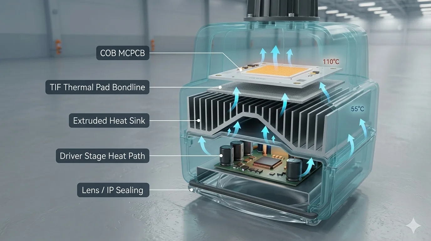
LED thermal management
LED thermal management connects the LED module, driver, thermal interfaces and housing. Review the MCPCB-to-heat-sink path, optical-material compatibility and molded housing options for the complete luminaire.
LED thermal management connects the LED module, driver, thermal interfaces and housing. Review the MCPCB-to-heat-sink path, optical-material compatibility and molded housing options for the complete luminaire.
Ziitek supports LED luminaire OEMs across COB modules, driver housings, and outdoor sealed fixtures with a TIM portfolio tuned for low optical bleed, predictable interface resistance, and the long L70/L90 horizons that solid-state lighting buyers underwrite.
Scene challenges
Solution value
Every claim a luminaire makes — efficacy, L70 hours, color stability, warranty length — ultimately resolves to one number on a TM-21 worksheet: junction temperature. The lighting team can pick the brightest LED, the most efficient driver, and the prettiest optic, but if the thermal interface between MCPCB and heatsink is wrong, lumen depreciation accelerates and the marketing curve flattens. Ziitek's role in an LED program is rarely glamorous, but it is repeatedly the lever fixture engineers reach for once the obvious mechanical choices are locked.
MCPCB to heatsink. This is the primary path and the one most often under-specified. A soft, gap-filling pad with low compression set wets micro-textured aluminum without pumping out under thermal cycling. We help teams match pad thickness to screw pattern and casting flatness — small adjustments here can move junction temperature several degrees, which compounds across thousands of operating hours.
COB to coin or slug. High-flux COB arrays concentrate heat into footprints smaller than a fingernail. A high-conductivity pad or a thin PCM layer can shave critical degrees off the chip-on-board interface, which is often the bottleneck in slim downlights and architectural spots.
Driver to housing. Constant-current drivers, surge magnetics, and PFC stages sit inside sealed driver boxes where height tolerance and creepage distances drive the stack. We supply gap pads tuned for voltage standoff conversations and PCM where electrolytic-adjacent heat spikes need a buffer.
Large castings and outdoor enclosures. Street, high-bay, and tunnel fixtures use die-cast aluminum housings with substantial CTE mismatch versus the LED board. Thermal graphite sheets help spread heat across the casting interface, and low-bleed silicone pads tolerate the stagnation temperatures of IP-rated enclosures without outgassing into the optics chamber.
Linear luminaires, troffer panels, and strip fixtures use long, narrow MCPCBs that benefit from cut-to-width roll formats rather than die-cut sheets. We stock pad materials in widths that align with common LED board geometries, so manufacturing engineers can spec a continuous roll and trim in-line instead of managing thousands of individual die-cut parts. For lower-volume architectural and stage programs, die-cut and kiss-cut shapes are available with reasonable minimums.
Many lighting programs depend on DLC listings, utility rebates, or regional efficiency incentives that require documented thermal margins. Our application engineering team can provide the interface-resistance data and material chemistry documentation that supports those filings without forcing the OEM to derive numbers from scratch.
Ziitek's experience with industrial fiber lasers, photonics modules, and high-power emitter cooling translates directly to the upper end of the LED market — stage wash heads, projection engines, large-venue architectural lights, and specialty fixtures where heat density approaches industrial-photonics levels. The same chemistry families and cleanliness discipline that qualify for laser modules apply when an LED program pushes into 100 W and beyond.
Send us the MCPCB drawing, heatsink alloy, target lumens, and any optical adjacency constraints (lens chemistry, reflector finish, seal path). We will recommend pad and PCM thicknesses, ship qualification samples, and align the documentation package with whatever reliability model your team is building.
Application engineering
LED thermal management also includes the housing itself, beyond the TIM between the LED board and heat sink. Evaluate it as a molded thermal component. Compare conductive plastic with the current aluminum design using full-assembly thermal, electrical and manufacturing criteria.
Application design guidance. Thermal, electrical and manufacturing results depend on the material grade, housing geometry and test conditions. HDT is not a continuous-use temperature rating.
From rapid prototyping to full-scale production — our engineers are ready to design a custom thermal solution for your application. Trusted by 7,000+ clients across EV, 5G, and consumer electronics.