Thermal Test Vehicle Heater: Polyimide Spec Guide
How to specify a polyimide heater for a thermal test vehicle: effective area, watts from heat flux, supply voltage, bonding to copper, sensing and control.
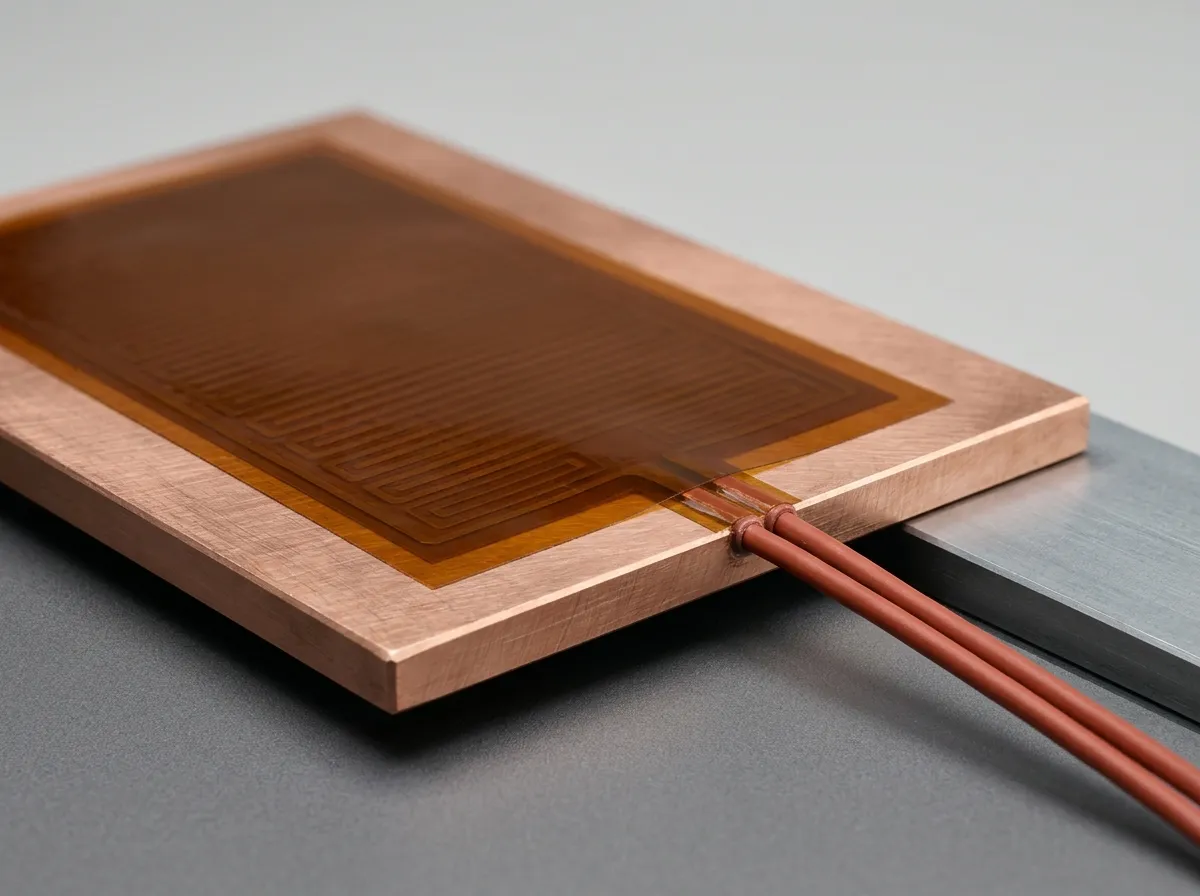
What a Thermal Test Vehicle Heater Actually Has to Do
A thermal test vehicle stands in for a real device so a cooling stack can be measured without powered silicon. Its heater has a narrower job than making heat: it must deliver a known flux across a known area, at a known temperature, repeatably.
Two families exist. Package-level vehicles mount a thermal test chip — resistor heaters plus RTD or diode sensors built into the die — in a real package footprint. Fixture-level vehicles bond a heater to a plate and sense temperature where the acceptance criterion lives. This article is about the second.
That purpose sets the measurement chain. Where the fixture exists to compare junction-to-case resistance, JEDEC JESD51-14 already defines the method: the transient dual interface technique for single-path heat flow. That is the die-level route; a film fixture instead reports plate-to-coolant resistance, which is why the next section matters. A heater with an unknown bond interface, or one whose power drifts as it warms, corrupts the chain before the first data point.
Two Heat Source Architectures, and Where a Film Heater Fits
The gap between the families is easiest to see in numbers. Nanotest's TTV10 datasheet rates zones at 3.2 W/mm² and hotspots at 10 W/mm² — 320 and 1,000 W/cm² — and its TTV200 datasheet goes to 6.5 W/mm². KLC quotes up to 500 W/cm² for its high-power vehicles. Those are die-scale figures: at Nanotest the heat is generated in a resistor array on the die itself; at KLC it comes from a resistor pattern in an ultra-thin dielectric stack sized to the package footprint. The die-level mechanism is the one the Nanotest presentation given at Fraunhofer ENAS sets out.
A bonded polyimide film sits roughly 500 to 3,000 times below the zone ratings. ZIITEK's KHEAT-PI TTV application brief publishes 0.1–0.6 W/cm² recommended and 1.0 W/cm² maximum, over −40 to 130 °C at 1–220 V AC/DC, in 0.1–0.52 mm film. A film heater is a plate-level flux source, not a die emulator.
Two questions decide which you need. Flat area with a defined average flux — a cold plate, a heat sink base, a TIM stack? A film on a plate is cheaper, thinner, and buildable in a machine shop. Gradients at millimetre scale, a power map across a die, specific hotspots? Then you need a die-level vehicle — a test chip, or a multi-zone heater stack sized to the package.
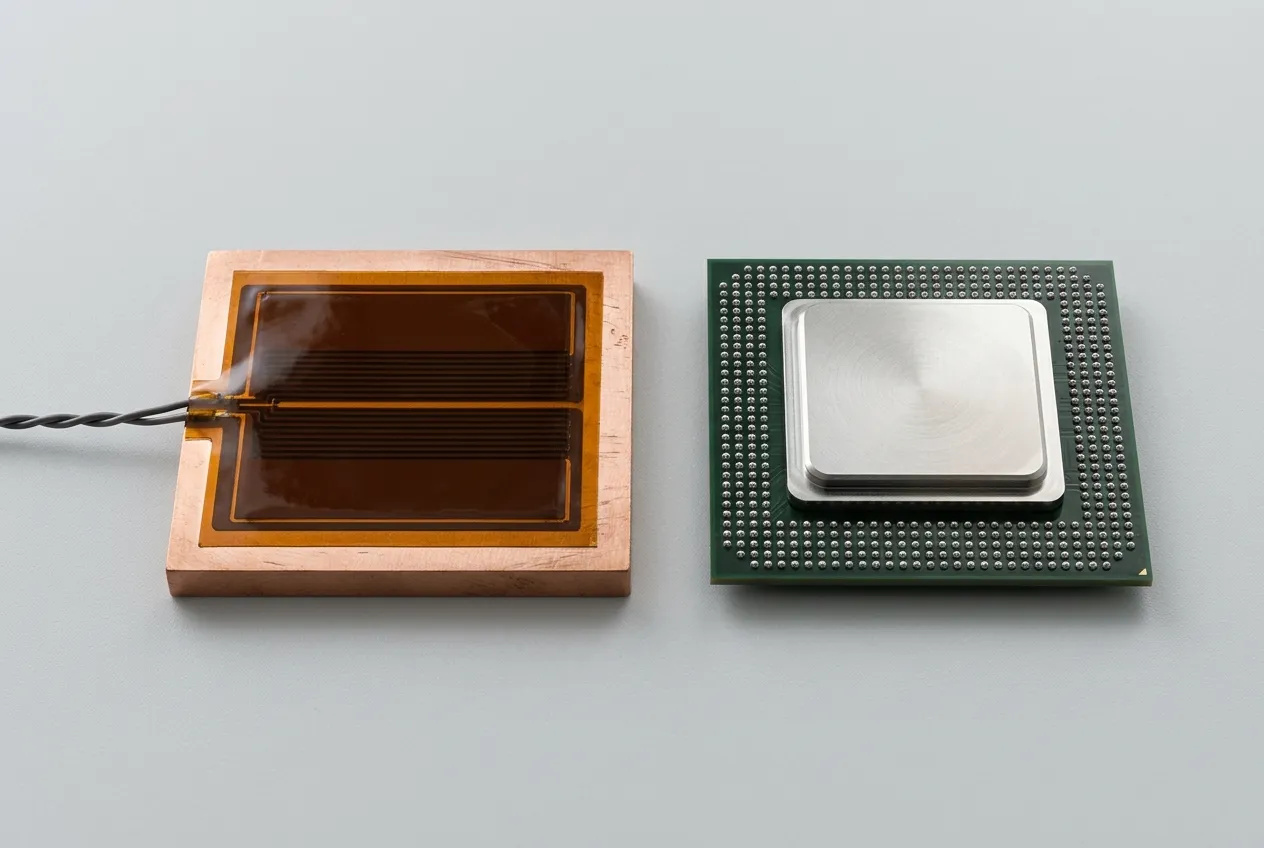
If the film itself is still open, that is a separate question, covered in the polyimide heating film design guide; the heating film hub indexes the other constructions.
Effective Area: The One Number That Sets Everything Else
Power density is watts divided by area, so the area decides whether the fixture runs at 0.35 or 0.43 W/cm².
The area that counts is heated area, not outline. A film has an unheated border where the dielectric seals the element, cutouts for mounting hardware, and a lead exit. None of it generates heat; all of it appears in the drawing dimensions.
Take a 120 × 120 mm film with a 5 mm border and a 20 × 30 mm lead cutout inside the heated region. Outline: 144 cm². Heated region: 110 × 110 mm = 121 cm², minus 6 cm² = 115 cm². Put 50 W into it and you are at 0.35 W/cm² on the outline, 0.43 W/cm² on the heated area — a quarter apart, with nothing in the record to show it.
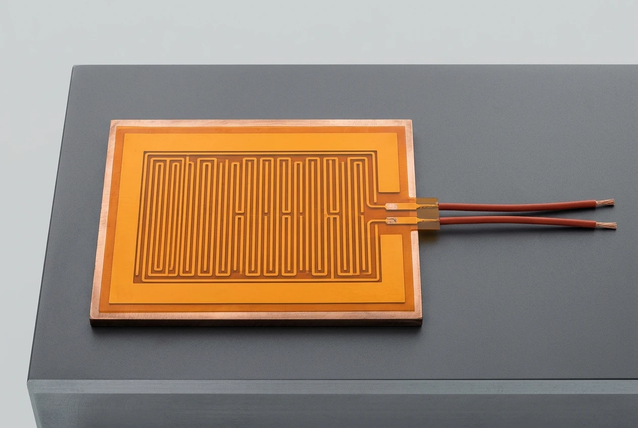
| Counts as effective area | Does not count |
|---|---|
| Etched element inside the seal border | Unheated dielectric border |
| Area under the device or cold plate footprint | Lead exit and solder tab |
| Element area around cutouts, measured net | Mounting holes and slots |
| — | Outline dimensions on the drawing |
Two limits on that number. It is an average, so local flux follows the trace pattern — a centre-weighted serpentine and an even grid are different heaters at identical total watts. And the heated area's boundary is not adiabatic: heat leaves through the plate edges, which is why a perimeter guard heater or extra insulation changes the map you end up measuring.
From Heat Flux Target to Watts, Volts and Amps
Three equations carry the electrical specification: P = q″ × A, P = V²/R, and I = P/V.
The same 115 cm² film at 0.43 W/cm² needs 50 W. On 48 V, R = V²/P ≈ 46 Ω and current ≈ 1.0 A. On 12 V, R ≈ 2.9 Ω and current ≈ 4.2 A. Same watts, very different installation: 4.2 A through a thin lead and a small connector is a voltage-drop and heating problem. That is why the supply belongs in the same conversation as the element design.
| Case | Effective area | Flux | Power | Supply | Element R | Current |
|---|---|---|---|---|---|---|
| A | 115 cm² | 0.43 W/cm² | 50 W | 48 V DC | ≈46 Ω | ≈1.0 A |
| B | 115 cm² | 0.43 W/cm² | 50 W | 12 V DC | ≈2.9 Ω | ≈4.2 A |
| C | 36 cm² | 0.6 W/cm² | 21.6 W | 24 V DC | ≈27 Ω | ≈0.9 A |
Assumptions: flux is an average, resistance is at room temperature, supplies are ideal. Real installs lose voltage in the leads, so measure power at the heater — four-wire sensing or a series shunt, as the Purdue TTV work published at ITherm 2024 does per zone.
Resistance also rises with temperature, so a fixed-voltage supply delivers a few percent less power at soak than cold. Either control power or record the drop.
If one of those numbers lands near an edge — 4.2 A through a thin lead, or a small plate pushed to 0.6 W/cm² — send these numbers for a design review before an element is ordered, and let the lead and connector be sized against the real current.
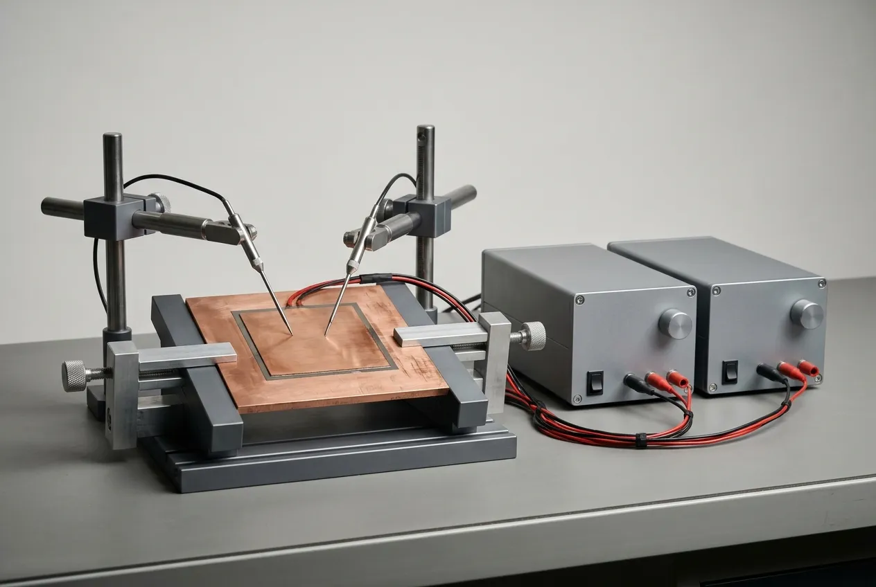
Bonding the Film to a Copper Plate
Copper is not just a mounting surface. It spreads heat laterally so the face your device sees is more even than the trace pattern beneath — copper conducts at roughly 400 W/m·K — and it gives the assembly enough mass for a controller to act.
The bond line is where fixtures quietly go wrong. Adhesive tape is easiest to apply and least tolerant of contamination and shear at temperature; structural adhesive trades reworkability for a thinner, more consistent layer; mechanical retention avoids adhesive but concentrates pressure at the fasteners. What changes the reading is bond line thickness, voids in it, and plate flatness. A void under the device footprint shows up as a local hotspot and as a slow drift as the assembly cycles.
The ceiling belongs to the whole assembly: the published configuration is rated to 130 °C under its specified attachment and heat-sinking condition, and the family data sheet's 180 °C figure applies to the unbonded film, not to this bonded build. Above that, the honest next step is a different construction — silicone rubber pads, which in this catalogue are rated to 200 °C with a compatible adhesive system, and mount differently.
Sensing and Control: Closing the Loop Around the Fixture
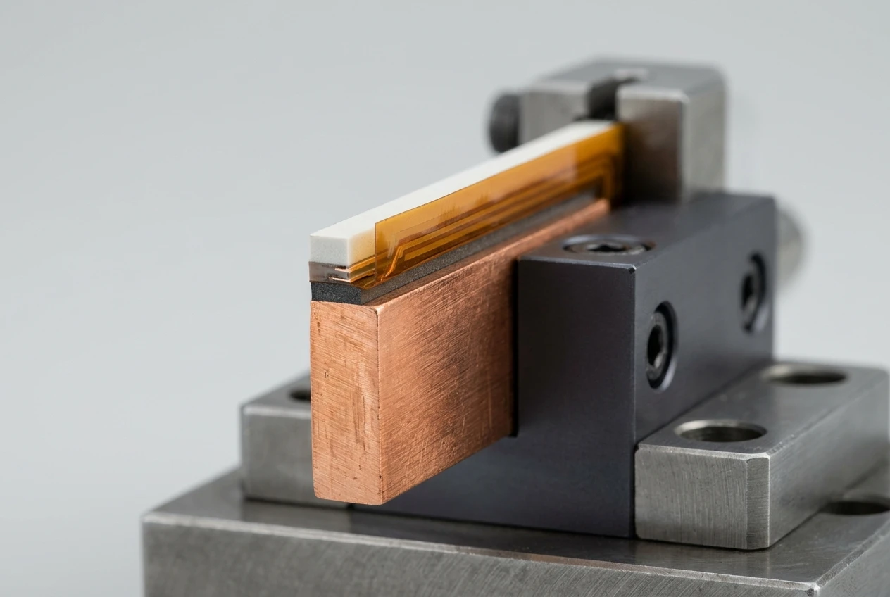
A control loop holds one temperature. Which one it holds depends on where the sensor sits, and this is where fixture numbers most often become untraceable.
Four locations are defensible: a thermocouple bonded inside the device footprint reads the face the device sees; a sensor in a shallow drilled hole reads metal near the heater; one on the film's back face reads the heater; a probe in the coolant reads the sink. The sensor driving the loop must be the one whose temperature appears in the acceptance criterion. A second sensor elsewhere is an independent over-temperature trip, not a second opinion on the same number.
Thermocouples are the default: small, fast, cheap, accurate to a degree or two — the scale of most decisions. Resistance sensors are more stable and resolve finer, at the cost of size and a three- or four-wire connection. Attachment matters more than the choice; a probe held on with tape reads the air gap.
A PID loop on a solid-state relay is standard. Keep the sample interval short against the assembly's time constant or the loop oscillates; limit integral action during heat-up or it overshoots soak; and hard-wire the over-temperature cut-out so a failed relay cannot run the heater to its limit. Heat-up rate is set by power density, not by the controller: at 0.5 W/cm² a thick plate is slow, and if ramp time is a requirement, it is a power requirement.
An Acceptance Run You Can Repeat Next Month
An acceptance run is not a number; it is a number the next person can reproduce.
Define steady state up front: a stated maximum rate of change over a stated interval, applied to every point. Record the grid — centre, corners, edge midpoints, points inside the device footprint — and log ambient temperature, coolant inlet and flow, voltage and current at the heater, attachment torque, and run number.
Run it three times on different days and report the spread. A centre point that repeats within a degree while corners move by five is telling you about edge losses, not heater quality. If the fixture will be cycled rather than soaked, repeat the run across cycles and record the drift between them: a reading that moves after a hundred cycles is the result, not an anomaly. Without a measured surface map, do not claim uniformity.
When the Fixture Needs a Dedicated High-Flux TTV
Four signals put you past a film fixture: a target above 1 W/cm², an acceptance criterion that depends on a power map across a die, millimetre-scale hotspots, or kilowatt totals.
Past that line the references are die-level vehicles, built either on a test chip or on a high-power heater stack. Nanotest's TTV10 drives four zones and six hotspots at up to 60 V and 8.5 A per zone with sixteen on-die sensors; its TTV200 datasheet lists up to 48 zones, 7,400 W and 112 on-die sensors. KLC's thermal test vehicles are heater-based rather than silicon: they run from 12 to 600 V with multi-zone control, integrate RTD, NTC or thermocouple sensing, and quote up to 500 W/cm². Either route implies a control unit and a calibration path, plus a test board on the chip-based side — a budget of a different order from a bonded film and a bench supply.
| Requirement | Bonded film on a plate | Dedicated high-flux TTV |
|---|---|---|
| Flux | 0.1–1.0 W/cm² class | 300–1,000 W/cm² class |
| Heated area | Large plate, arbitrary outline | Die-scale, package footprint |
| Sensing | External thermocouples or RTDs | On-die sensors, many channels |
| Zoning | One or a few circuits | 4 to 48 driven zones |
| Electronics | Bench supply, PID, SSR | Control unit and calibration; test board on chip-based vehicles |
The Specification Sheet to Send a Heater Manufacturer
Everything above collapses into a short list. Send these and a supplier can quote a design rather than a guess.
| Field | What to state |
|---|---|
| Effective heated area | cm², measured net of border and cutouts |
| Outline and cutouts | Dimensions, lead exit position, mounting holes |
| Flux target | W/cm² at soak, average or peak |
| Total power | W at soak, with the voltage it assumes |
| Supply | V, AC or DC, fixed or adjustable |
| Current | A, plus lead length and connector type |
| Element resistance | Ω at room temperature, or the tolerance you can accept |
| Mounting surface | Material, thickness, flatness, attachment method |
| Temperature range | Operating range, plus adhesive or bond system assumed |
| Sensing | Sensor type, count, positions, attachment |
| Control | PID with SSR or open loop; over-temperature scheme |
| Acceptance | Steady-state criterion, measurement grid, repeatability target |
Two fields do most of the work: effective area decides the flux, supply decides resistance and current.
At sketch stage, five inputs start the conversation: effective heated area, total power at soak, supply voltage, the copper structure the film will bond to, and the acceptance criterion. Send that five-input specification for a quotation. Published limits are on the KHEAT-PI page, and the wider family under film heating elements.
FAQ
Can a polyimide heater be the heat source in a thermal test vehicle?
Yes for a fixture-level vehicle: a plate carrying a defined average flux into a cold plate, TIM stack or heat sink base. No for a die-level vehicle that reproduces a processor power map at hundreds of watts per square centimetre. The published film configuration tops out around 1 W/cm² — a different regime, not a smaller version of the same one.
What power density should I specify?
Start from the flux your acceptance criterion needs, then check it against the construction limits: 0.1–0.6 W/cm² recommended, 1.0 W/cm² maximum here. The maximum is a construction limit under a specified attachment, not a target and not a continuous rating for arbitrary cooling.
Do I size the heater by outline or by heated area?
By heated area: the etched element inside the seal border, net of cutouts, excluding the lead exit. Using the outline understates flux, so the fixture actually runs hotter than the plan says — closer to the maximum than you intended — and the record cannot be reconciled afterwards.
How do I hold a plate at temperature?
A PID loop on a solid-state relay, with the sensor where the acceptance criterion is measured, an integral limit for heat-up, and an independent hard-wired over-temperature cut-out. Record measured power at the heater, not the supply setting: lead drop and temperature coefficient both move it.