Polyimide Heater Design: Custom Watt Density & Zones
A polyimide heater is an etched-foil circuit sized like a resistor. This guide covers construction, watt-density math, voltage, zones, and a spec checklist.
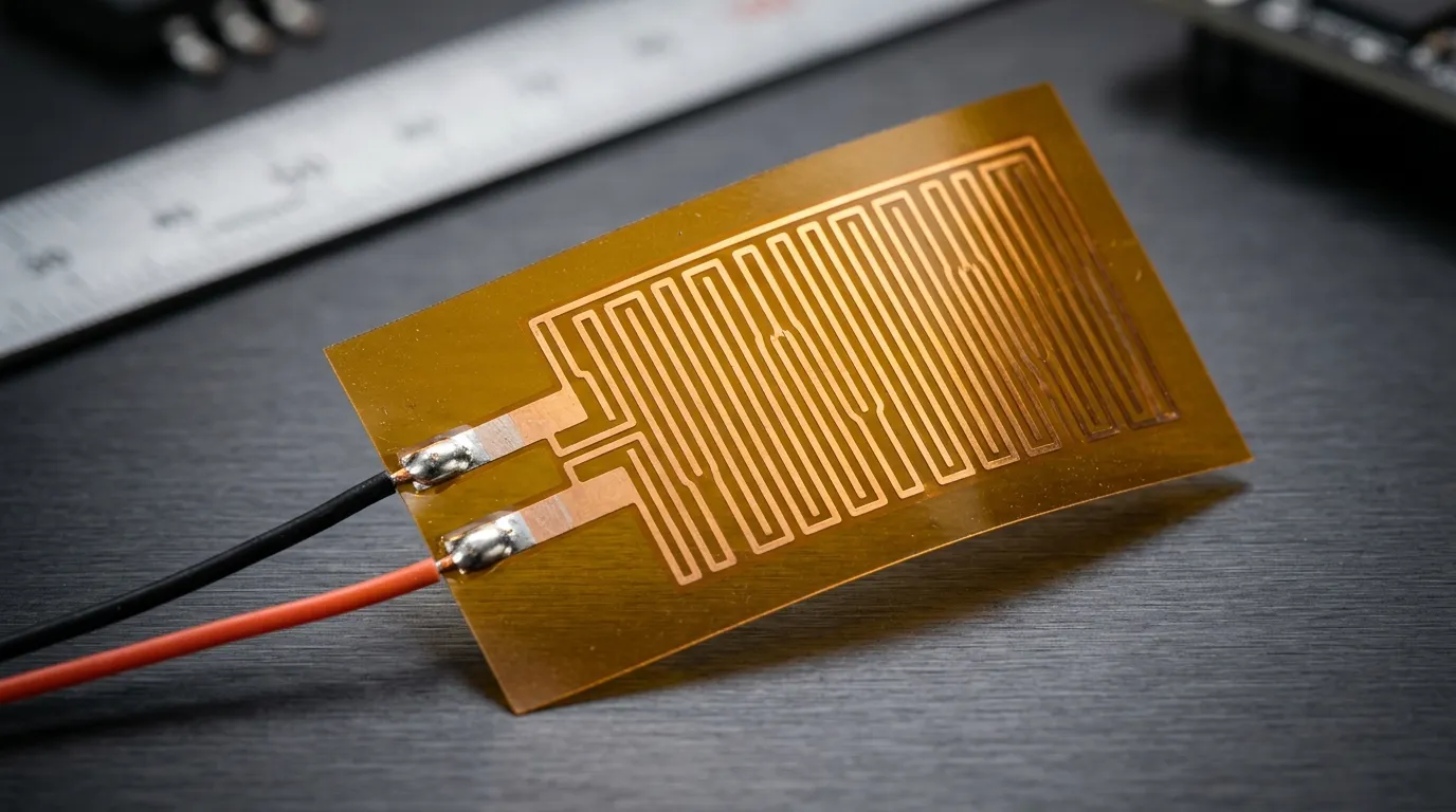
Designing a product that needs heat in a space only fractions of a millimeter thick — a battery cell face, a camera housing window, a fluidics cartridge — usually lands on the same question: which flexible heater, and how do we make it deliver exactly the watts we need, exactly where we need them?
A polyimide heater answers both halves. It is a flat resistive circuit etched onto polyimide film — the amber, high-temperature polymer many engineers know under the Kapton brand name (developed by DuPont; the Kapton® film business is now part of Qnity Electronics, spun off from DuPont in November 2025). The element is thin enough to sit between battery cells, light enough to ignore on a gimbal, and because the circuit is defined by etching, its wattage, voltage, and heat distribution are design variables rather than fixed properties. Our heating film and heater pad hub frames the wider category; this guide stays on the polyimide (PI) construction and shows how to turn an application requirement into a custom polyimide heater specification.
What a Polyimide Heating Film Actually Is
A PI heating film is a laminate: two or more thin polyimide layers with a flat metal-foil resistive element between them. The foil — typically nickel or a nickel alloy such as Inconel — is etched into a meandering circuit pattern the way a PCB trace is made, then sealed between the polyimide layers with a high-temperature adhesive. Two flat leads are attached at one edge, and the finished film is 0.1 to 0.5 mm thick with the flexibility of photographic film.
Three properties of that construction drive every design decision:
- The heat source is a flat trace, not a wire. Etched foil spreads the resistive path across the whole area, so heat is generated where the film lies rather than along a single line.
- Polyimide is the carrier and the insulator. It withstands temperatures far above what the surrounding adhesives tolerate, resists most solvents and radiation, and insulates the live circuit from whatever the film is bonded to. Material data published by the film's current supplier (Qnity Electronics, formerly DuPont Electronics — Kapton polyimide film) shows the film family rated for continuous high-temperature service with good dielectric strength — exactly why it is the default carrier when thinness and temperature combine.
- The circuit pattern is the spec. Because the resistive path is drawn and etched, its width, pitch, and geometry are free variables. Uniform wattage, denser zones at edges, or several independent circuits on one film are all the same manufacturing step: draw the pattern differently.
The result is a heating element that behaves like a flexible thermal circuit. The Kheat PI film from ZIITEK, as a working example of the construction, is built on modified PI film, spans 0.1 to 0.52 mm thickness, bends down to a 0.8 mm radius, and uses an etched pattern chosen for heating uniformity (Kheat PI film heating element).
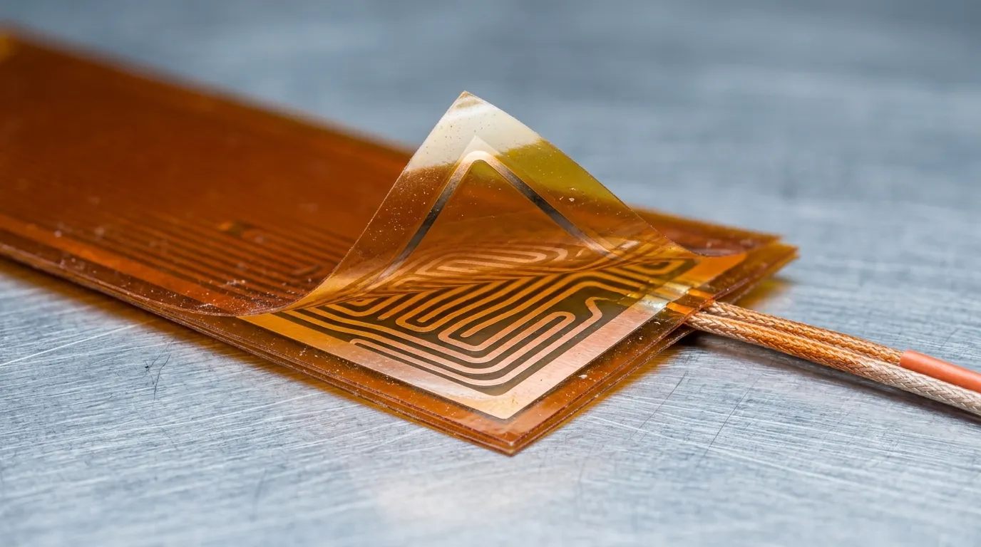
Peel back the top polyimide layer and the whole story is visible: one flat etched foil circuit, sealed between two thin insulating films.
Thin Film or Silicone Pad? A Two-Question Decision
Check the construction family before designing anything. Flexible heaters come in two dominant forms, and they are not interchangeable:
| Spec | Polyimide (PI) film | Silicone rubber pad |
|---|---|---|
| Thickness | 0.1–0.5 mm class | 1.1–5 mm class |
| Flexibility | Ultra-thin, bends to ~1 mm radius | Flexible but thicker |
| Ruggedness | Thin; protect from abrasion and puncture | Fiberglass-reinforced, abrasion and moisture resistant |
| Typical fit | Tight gaps, low mass, optics, medical | Harsh environments, battery pack floors |
The decision rule takes two questions. Is space or mass the constraint? If the heater must sit between prismatic cells, behind an optical window, or inside a handheld instrument where every tenth of a millimeter counts, PI film wins — nothing else delivers useful watts at 0.2 mm. Will the heater see mechanical abuse? Silicone pads embed the same kind of element in a fiberglass-reinforced jacket and shrug off vibration, grit, and rough handling that would eventually damage a thin film; ZIITEK's Kheat SP silicone heating pad is the companion product for those jobs. When both questions point to film, keep reading.
Designing a Polyimide Heater: Start with Watts and Volts
Every custom PI heater is, electrically, a resistor — and two equations govern the whole design.
Power equals voltage squared over resistance (P = V²/R). Decide the bus voltage, and the resistance of the etched circuit is fixed by the watts you need. Power density equals watts over heated area (W/cm²). Divide total watts by the film area to check the design against what the film can deliver.
A short example with round numbers. Suppose a 24 V DC bus and a 100 W heater: R = V²/P = 576/100 ≈ 5.8 Ω. Current follows from Ohm's law, I = V/R ≈ 4.2 A, which sizes the leads and connector. If the heated area is 400 cm² (a 20 × 20 cm film), the watt density is 100/400 = 0.25 W/cm² — inside the 0.1–0.6 W/cm² band ZIITEK's Kheat PI datasheet recommends, and well under its 1.0 W/cm² maximum. That band is specific to the construction, not an industry-wide rule: the ceiling depends on the foil, the adhesive and the heat sinking, and the Epec review linked below cites PI constructions rated up to 50 W/in² (≈7.75 W/cm²). These are illustrative numbers; the datasheet of the film you select is the authority for its own limits.
Watt density is where first designs go wrong in both directions. Too low, and the heater cannot hold temperature against losses, so it runs at full duty cycle and still underdelivers. Too high, and heat builds up faster than the application carries it away: the adhesive degrades, and delamination or adhesive failure follows. That failure chain — excessive watt density, layer delamination, shortened life — is documented in Epec's engineering review of polyimide flexible heater limits (Epec blog, temperature and power limits). Size for steady-state losses, and treat the recommended band as the starting assumption rather than the maximum.
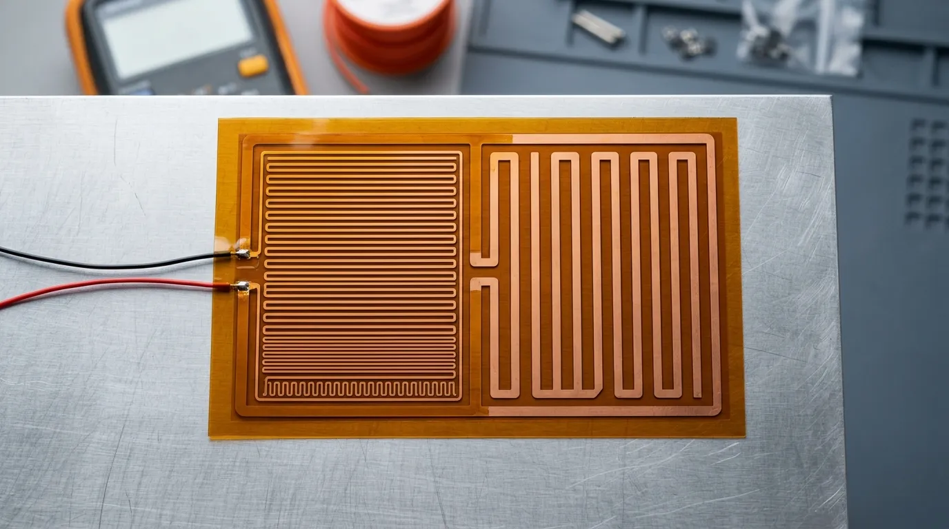
Two zones, one film: the etched pattern density is a free variable, which is what makes localized heat possible.
Custom Voltage: Match the Circuit to the Bus
Because resistance is set by the etched pattern, the same physical film can be produced for different voltages by redrawing the circuit. A film driven at 12 V carries more current for the same watts than one driven at 220 V, so the pattern, foil, and leads shift together. Polyimide heaters are built for AC or DC across a wide span — the Kheat PI datasheet covers 1–220 V AC/DC — so the constraint is almost always the bus your product already has, not the heater.
Three details belong on the drawing:
- Resistance tolerance. Etched circuits carry a tolerance, typically ±10%. At a fixed bus voltage, power scales as 1/R, so that tolerance turns into a wattage band of the same size in the opposite direction — a nominal 100 W film can land anywhere from roughly 91 to 111 W — so budget for it in the thermal design.
- Leads carry the current. A 4 A heater needs different leads than a 0.5 A heater. Specify length, gauge, and termination (solder pads, terminals, connectors) up front; lead-pull ratings exist because leads are the most common mechanical failure point in thin films.
- Dielectric strength is the safety spec. Polyimide plus the adhesive bond is all that separates the live circuit from your product. If the film contacts a conductive surface, a battery cell, or anything where a fault matters, state the dielectric breakdown voltage and insulation resistance you require, and verify them at the test voltage your standard demands.
Custom Zones: One Film, Several Heat Profiles
Pattern freedom also enables zoning: several independent circuits on one film, each with its own resistance, leads, and therefore its own power. This is what turns a heating film from "a heater" into "a thermal design."
Three zoning patterns cover most real needs:
- Uniform heat — one circuit over the whole area at equal pitch. Right for a flat plate that must sit at one temperature.
- Edge-compensated heat — pitch tightened near edges and corners. Edges lose heat faster than the middle, so a denser perimeter pattern holds a more uniform surface temperature.
- True multi-zone — two or more electrically separate circuits on the same film, running at different power or switching independently: a battery film that heats a cold module end harder, an optical window heater with a dense ring around the glass and a sparse center, a heated stage with its own controlled hot spot.
Multi-zone films cost a little more and carry more leads, so use them when the thermal problem is genuinely non-uniform. If one corner of the part is always cold, a zoned film beats a bigger uniform heater that overheats the rest of the surface to fix the spot. Send the manufacturer a sketch of where heat is and is not wanted, not just a total wattage.
Temperature Sensing and Closed-Loop Control
A resistive heater with no control keeps heating past its target — a safety and reliability issue, not a nuance. Polyimide films integrate sensing at the same lamination step: an NTC thermistor or RTD bonded to the film surface, or a bimetallic thermostat that opens the circuit at a set point. The control architecture is the same as for any heater:
- Sense where the temperature matters — on the object or at the film, placed to represent the coldest or most critical point.
- Switch with a controller or thermostat rated for the inrush current of a cold element.
- Protect with an independent over-temperature cutoff, so a sensor failure cannot leave the heater energized.
An NTC adds no meaningful thickness at this scale. Sensor integration is an option on custom films rather than a given, so confirm the sensor type, placement and bonding against your supplier's datasheet before you design the control loop around it.
Mounting and the Real Temperature Limit
Mounting decides where the heat goes and how hot the system can safely run. Three families cover nearly everything:
- Pressure-sensitive adhesive (PSA) — film arrives with adhesive and liner, is pressed on, and conducts through a thin bond line. Simplest assembly, but the adhesive is the thermal and temperature bottleneck.
- Lamination or overmolding — film embedded into the product structure, under a skin or between composite layers. Best thermal coupling; planned at design time.
- Mechanical clamping or potting — film held by a clamp, bracket, or cured compound. Right when rework must stay possible.
This is also where the honest temperature answer lives. The polyimide film itself tolerates high temperatures, but the system limit is usually set by the adhesive and the bond, not by the film. Adhesive-backed films are typically rated for continuous use around 200 °C, with the limit depending on the temperature stability of the specific adhesive — the Kheat PI datasheet states it exactly that way. If your application runs hot for sustained periods, state the continuous and peak temperature with duty cycle and let the manufacturer select an adhesive rated for it — or drop the adhesive and mount mechanically. Designing to the film's own maximum while ignoring the adhesive is how "it should handle this temperature" becomes a field failure a year later.
Where a Polyimide Heater Earns Its Place
Battery warming and cold-weather preheat
Lithium cells charge slowly and age faster in the cold: below roughly 10 °C charging current must be limited, and sustained cold operation accelerates capacity fade, as surveyed in the battery thermal management literature (Hwang et al., 2024). The fix is to warm the pack before and during charging. A thin film bonded to the module base or between prismatic cells raises the cells into the 15–25 °C window with almost no added stack height — the 0.1–0.5 mm class fits where a thicker pad cannot. The full materials picture, placement, and the heating layer's role in the stack are covered in our EV battery pack thermal management guide, and ZIITEK's EV and new-energy industry solutions page shows the film as the direct-integration heating layer in pack designs.
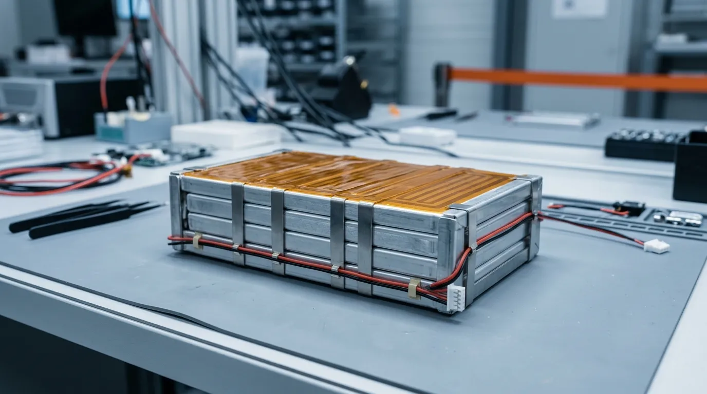
In a cold-weather pack the film goes where the cells are: flat against the module, adding almost nothing to the stack height.
Optics, 5G enclosures and condensation prevention
Enclosures holding cameras, lenses, or optical modules fail quietly in the cold: when a cold-soaked window meets humid air, condensation or frost forms on the optics. Heating holds the window above the dew point, and film is well suited because it can be etched as a ring around the glass, adds negligible mass to a pan-tilt or gimbal assembly, and runs at low voltage. The same logic applies to outdoor 5G radios and optical modules, where sealed housings trap moisture unless the cold surfaces inside are held warm — sealing and heating are complementary, which is why IP-rated enclosure sealing (silicone foam gaskets for electronics, IP68) and window heating appear together in outdoor telecom and camera designs. For the thermal-and-EMI side of 5G and optical equipment, see our thermally conductive EMI absorbing materials guide.
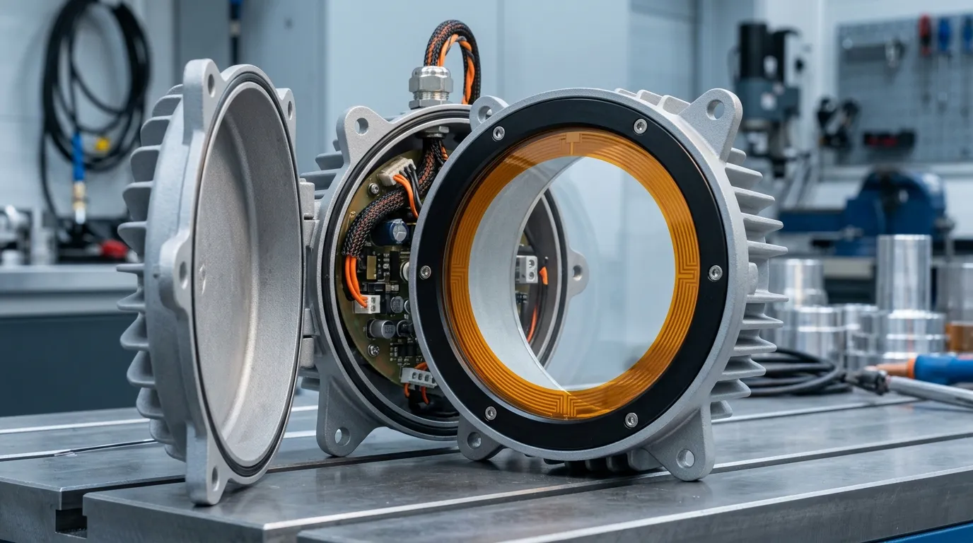
Keep the window above the dew point: a thin ring-shaped film behind the glass prevents the condensation that would otherwise blind outdoor optics.
Medical and analytical instruments
Diagnostic analyzers and fluidics systems need controlled heat in small volumes — warming a reagent, holding a microfluidic channel at temperature, cycling a reaction chamber. Polyimide film fits because it is thin enough to integrate behind a sample stage or into a cartridge, chemically resistant enough to survive cleaning protocols, and available with an embedded sensor for the tight loops these instruments demand. As elsewhere in this guide, the claims are about the heater: specify temperature accuracy, ramp rate, and duty cycle, then verify the film's range against the instrument's qualification profile.
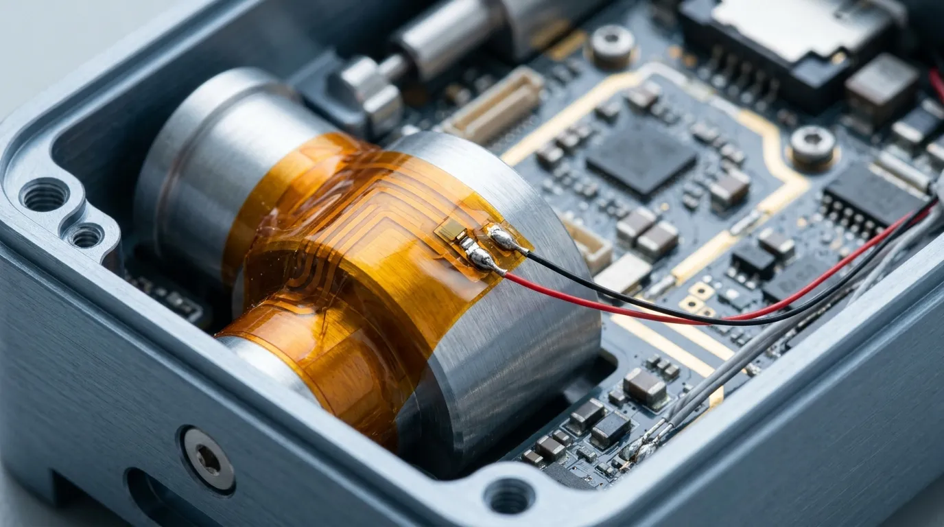
Inside compact instruments the film wraps the component that needs heat and carries its own sensor for closed-loop control.
Aerospace, vacuum and low-outgassing environments
Satellite equipment and vacuum-chamber instruments add a requirement most industrial applications never consider: outgassing. In vacuum, volatiles released by materials condense on sensitive optics and sensors. Polyimide is one of the low-outgassing polymers, which is why film heaters on PI carriers are the norm wherever TML/CVCM limits apply — the standard test method for those limits is ASTM E595. If your application is vacuum or space, state that requirement up front: it rules out silicone-rubber constructions and forces the adhesive selection to stay inside the outgassing budget.
The Specification Checklist: What to Send a Manufacturer
A custom film heater inquiry works from a surprisingly short list. Assemble these seven items and the design conversation starts at the right point:
- Geometry and thickness budget — footprint drawing, maximum thickness, any bends or wraps.
- Thermal target — surface temperature required, ambient range, warm-up time, continuous or intermittent duty.
- Total watts and area — target power, heated area, and the resulting W/cm² checked against the film's recommended band.
- Electrical specification — voltage (AC/DC), resistance or wattage with tolerance, dielectric and insulation requirements.
- Heat distribution — uniform, edge-compensated, or zoned; include the sketch of where heat is wanted.
- Control and integration — sensor type, lead length and termination, adhesive or mounting method.
- Environment and compliance — temperature extremes, vacuum or outgassing, flammability, RoHS/REACH or other documents your market requires.
Suppliers who build these films weekly also catch what a list misses. ZIITEK's application engineering team reviews drawings, patterns, and thermal budgets like this as routine work, and can map a Kheat polyimide film — or the silicone pad where abuse resistance matters more — to your assembly as one engineered part.
Frequently Asked Questions
What is a polyimide heater?
A polyimide heater is a flexible heating element made by sealing an etched metal-foil resistive circuit between thin layers of polyimide film — a flat, low-mass resistor that generates heat across its whole area and can be custom-shaped in power, voltage, and heat distribution.
How hot can a polyimide heating film get?
The film itself tolerates high temperatures, but the practical continuous limit of an adhesive-backed film is usually about 200 °C, because the adhesive and bond degrade first. Above that — or for sustained high-temperature duty — specify the adhesive system or use mechanical mounting.
Can a polyimide heater be bent or curved?
Yes. Thin PI film bends down to roughly a 1 mm radius — the Kheat PI film specifies 0.8 mm — so it conforms around cylinders, corners, and curved components without losing the circuit.
Is Kapton the same as polyimide?
Kapton is DuPont's former brand name for polyimide film — the brand and the film business moved to Qnity Electronics in DuPont's November 2025 electronics spin-off. A Kapton heater and a polyimide heater are the same construction family, and many suppliers use the terms interchangeably.
Can one film heat different zones to different temperatures?
Yes. Several electrically independent circuits can be etched on one film, each with its own resistance, leads, and control — the standard way to concentrate heat at cold corners or run regions at different power on a single part.
How long does a polyimide heating film last?
Datasheet service-life figures for film heaters typically land in the 5–10 year range. The real variable is how close operating temperature runs to the adhesive limit; staying well inside the rated band with controlled duty cycles is what makes the difference.