TIR26000-035: Thermal Impedance, Compression and Recovery Tests
Ziitek's October 2026 product introduction reports separate tests of TIR26000-035's thermal impedance, compressibility and thickness recovery. This material-validation reference helps engineers define tests for an interface with limited clamping force and a gap to accommodate. It does not describe a named customer's completed installation.
The selection problem
A pad must fit the mechanical stack as well as the thermal budget. The nominal gap, thickness tolerances and available force determine how much a pad can compress in an assembly. Thermal impedance must then be assessed at the applicable pressure and bond line.
The TIR26000-035 reference contains three distinct protocols: a pressure/thermal-impedance evaluation, a prolonged-compression recovery test and a repeated-compression test. Their sample sizes, timing and reported quantities should remain separate.
Test 1: Pressure, thermal impedance and compression
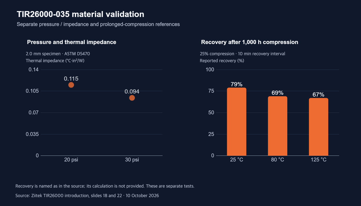
Slide 18 identifies ASTM D5470 testing and a sample measuring 25.4 × 25.4 × 2.0 mm. It reports the following readings:
Applied pressure | Reported thermal impedance | Reported compression |
|---|---|---|
20 psi | 0.115 °C·in²/W | 45% |
30 psi | 0.094 °C·in²/W | 61% |
In these two reported conditions, greater pressure was associated with greater compression and lower interface impedance. These are discrete readings, not a continuous design curve or guaranteed limits for every thickness and fixture.
The slide's numerical results should be used in preference to its broad description of “50–60%” compression over 20–30 psi: the listed 20 psi result is 45%, and the 30 psi result is 61%. Ask for the original pressure, thickness and temperature records before setting an assembly requirement.
The presentation does not provide a complete measurement-uncertainty statement or fixture description for these points. Do not assume that the same compression will occur in a different contact area, fastener arrangement or constrained part geometry.
Test 2: Recovery after prolonged compression
Slide 22 describes a different procedure using 25.4 × 25.4 × 2.0 mm specimens held at a thickness of 1.5 mm, corresponding to 25% nominal compression. Specimens were taken out at 250-hour intervals and measured after a stated 10-minute recovery period.
Compression-storage temperature | Reported recovery at 1,000 hours |
|---|---|
25 °C | 79% |
80 °C | 69% |
125 °C | 67% |
The presentation calls these values “recovery.” The exact calculation, treatment of the intermediate measurement cycles and full laboratory procedure should be supplied for a qualification comparison. These values must not be relabelled as standardized compression-set results or as a guaranteed installed gap.
This is a thickness-recovery test. It does not by itself establish thermal impedance after 1,000 hours, an electrical rating, vehicle qualification or a service-life claim.
Test 3: Repeated compression
Slide 23 describes 30 × 30 × 2.0 mm specimens compressed by 25% for five minutes, followed by two minutes of recovery before thickness measurement. The brief reports approximately 80% recovery after ten repeated compressions.
The different sample size, loading time and recovery interval distinguish this test from the prolonged-compression procedure. Ten laboratory cycles do not establish ten safe field reuses of a die-cut pad. Handling, surface contamination, damage and assembly load need separate consideration.
How to use the reference in a design review
Use the pressure data to frame a fixture test at the actual interface dimensions and load. Use the recovery data to define what thickness retention or recovery means for the application, including the calculation and time allowed after unloading.
For a production assembly, provide:
- Nominal gap, tolerance stack and contact-area drawing.
- Initial pad thickness and allowable assembled bond line.
- Available clamping force, pressure distribution and fastener arrangement.
- Thermal load, ambient range, cooling conditions and acceptance limit.
- Required recovery definition, loading duration and permitted rework process.
- Electrical-isolation and contamination requirements.
Review material properties and assembly results together. Higher compressibility alone does not establish lower device temperature, vibration resistance or longer service life.
Product range and qualification boundaries
The overview table in slide 9 lists TIR26000-035 at 0.5–2.0 mm nominal thickness and a 90 × 90 mm standard sheet. The test specimens described here are 2.0 mm thick; the results should not be transferred to every other thickness without validation.
The same table lists a recommended temperature range of −40 to 125 °C. That product-range statement is separate from any accelerated-aging condition elsewhere in the presentation. For a purchasing specification, request the current grade-specific datasheet and the applicable test report.
TIR26000-120 has a different thickness and interface-performance specification. Its published product page can help identify the other branch of the family, but its values must not be substituted for TIR26000-035.
Start a pressure-limited interface review
Send the TIR26000-035 interface requirements to Ziitek, or review the broader material range. Ask for the specific sample thickness, pressure curve, recovery definition and supporting report before establishing design limits.
Source: Ziitek TIR26000 graphene thermal pad product introduction, updated 10 October 2026, slides 9, 18, 22 and 23. These are manufacturer-reported material tests, not a customer installation or independent certification.
Cover charts: two separate Ziitek material-test references. Recovery is named as in the source, whose calculation is not provided; it is not relabelled as a standardized compression-set result.
Related thermal-management references
AI servse.webp)
Frequently asked questions
Does the reference show 50–60% compression at every pressure from 20 to 30 psi?
No. The listed points are 45% at 20 psi and 61% at 30 psi. They should not be replaced by a single range that hides those readings.
Is 67% recovery at 125 °C a compression-set rating?
The source identifies it as a recovery result under its stated procedure. A compression-set rating requires the applicable definition and test method; the labels cannot be exchanged.
Does ten-cycle recovery establish a pad-reuse allowance?
No. Controlled laboratory compression and removal/reinstallation of a finished pad are different procedures. Confirm the handling and rework limits for the intended assembly.
Can the 2.0 mm test results be used for a 0.5 mm part?
Not without grade- and thickness-specific evidence. Confirm the selected thickness and pressure in the actual stack.