Pressure and thermal impedance
Ziitek reports these separate readings for a 2.0 mm specimen using ASTM D5470. The values do not specify thermal conductivity in W/m·K.
| Pressure | Thermal impedance (°C·in²/W) |
|---|---|
| 20 psi | 0.115 |
| 30 psi | 0.094 |
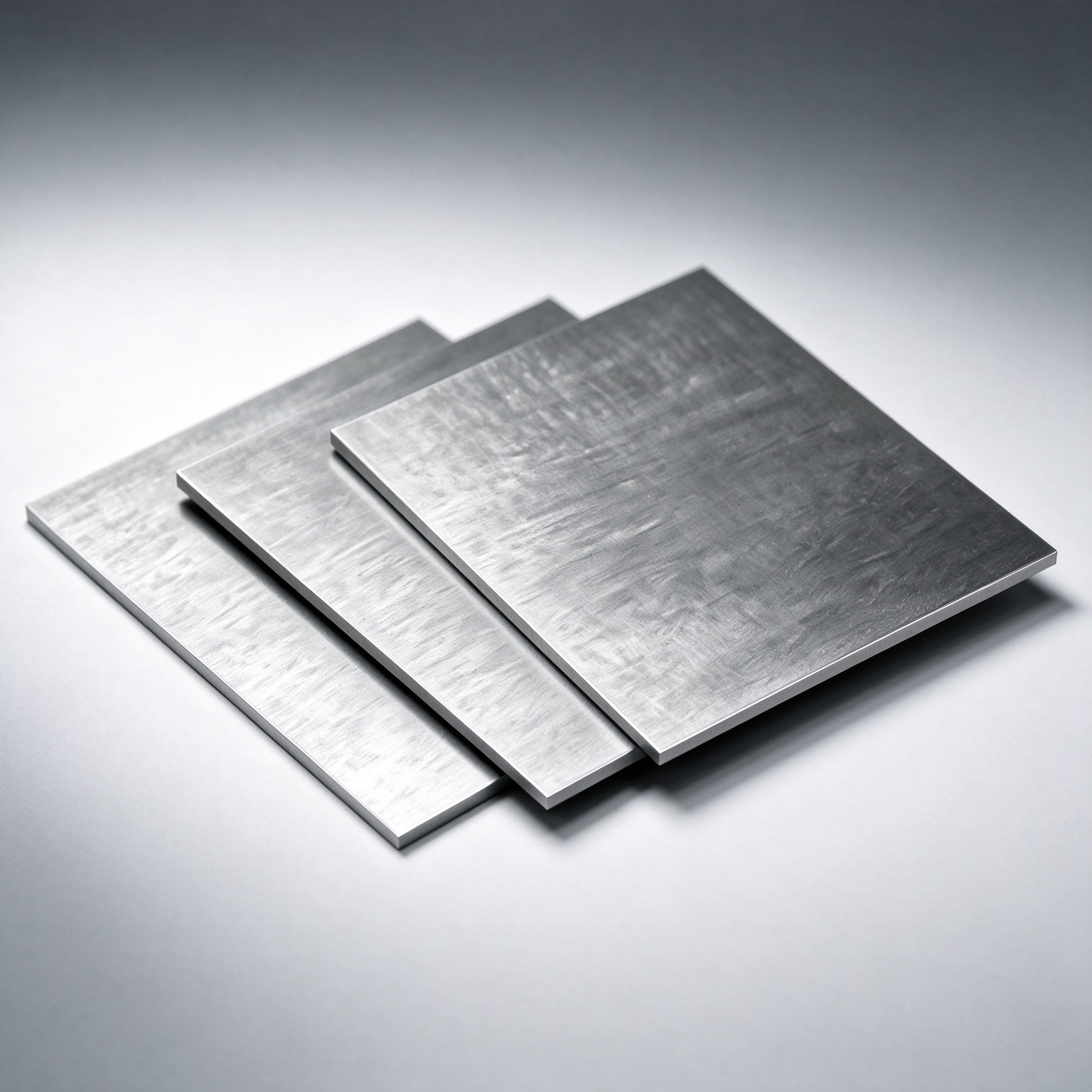
TIR26000-035 is a graphene thermal gap pad for component-to-heatsink interfaces in high-power-density electronics. The datasheet lists a 90 × 90 mm standard sheet in 0.50, 1.00 and 2.00 mm nominal thicknesses, with density ≤1 g/cm³ and a recommended operating range of −40 to 125 °C. At 50 psi using ASTM D5470, the listed thermal impedance is 0.030 °C·in²/W for 0.50 mm, 0.045 for 1.00 mm and 0.080 for 2.00 mm. Compare interfaces at the same thickness, pressure and measurement conditions. The material is electrically conductive and must not be used as electrical insulation. Send your gap, contact area and available clamping force for a grade-specific sample review.
Pressure-defined thermal performance
The datasheet specifies thermal impedance at 50 psi using ASTM D5470. Select the value for the required nominal thickness and compare it with your assembly pressure and compressed interface.
Specified rebound behavior
Rebound resilience is ≥80% for a 2.0 mm specimen compressed to 1.5 mm under ZKTM L005. Request the complete procedure; this value is separate from prolonged-compression recovery results.
Low oil bleed
The datasheet lists an oil bleed rate ≤1.5% using ZKTM G030. Check the applicable report and your assembly’s contamination limits.
Defined operating range
Recommended operating temperature is −40 to 125 °C. Density is ≤1 g/cm³. Validate the selected thickness and thermal interface under the intended hardware and environmental conditions.
Interface selection and validation
Use the selected thickness and the assembly's available pressure to evaluate TIR26000-035. The datasheet values at 50 psi and the lower-pressure reference tests describe different conditions. Compare like-for-like interfaces and confirm electrical clearance: the material is conductive and must not serve as electrical insulation.
Ziitek reports these separate readings for a 2.0 mm specimen using ASTM D5470. The values do not specify thermal conductivity in W/m·K.
| Pressure | Thermal impedance (°C·in²/W) |
|---|---|
| 20 psi | 0.115 |
| 30 psi | 0.094 |
A separate reference uses 25% compression for 1,000 hours and a 10-minute recovery interval. Reported recovery is 79% at 25 °C, 69% at 80 °C and 67% at 125 °C.
These readings are separate from the datasheet's ≥80% rebound resilience specification for a 2.0 mm specimen compressed to 1.5 mm under ZKTM L005. The presentation does not provide the recovery calculation; request the complete protocol before setting design limits.
Source: Ziitek TIR26000 product introduction, 10 October 2026, slides 18 and 22. Manufacturer-reported laboratory references; no customer installation or lifetime guarantee is implied.
The RTX 5080 reference includes both TIR26000-035 and TIR26000-120. Its readings describe the reported bench setup; they do not establish the temperature of a different assembly or make the two grades interchangeable.
RTX 5080 graphene pad comparisonReview TIR26000-035 for thermal interfaces in communication equipment, power devices, consumer electronics and data-center hardware. Match the selected thickness to the contact gap and mounting force, then qualify thermal performance and electrical clearance in the assembled device.
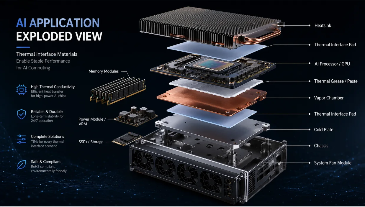
Servers · GPU · accelerators · DIMM
Data Center & AI Servers
High-flux silicon and dense PCBs — CPU/GPU bond-lines, VRM/DIMM/NIC interfaces, and accelerator cold-plate paths. Match grade against clamp force, TIM impedance, and rework cadence.
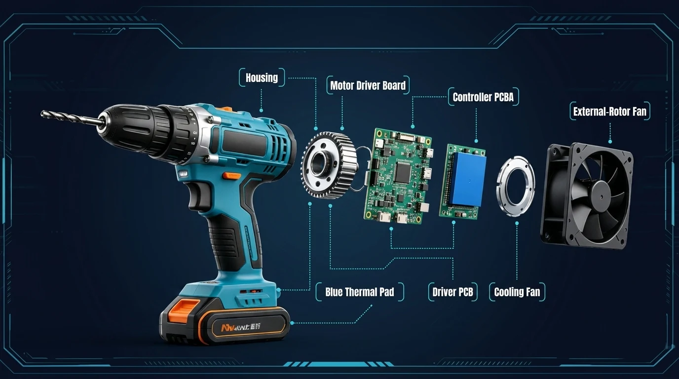
Drives · IGBT · controllers · sensors
Power Tools & Control Systems
Industrial controls, motor drives, power-stage IGBTs, and rugged modules — thermal interfaces, sealing, and encapsulation built for serviceable assemblies and harsh environments.
Values below are transcribed from the official datasheet. Use the linked PDF for sign-off and lot-specific CoA.
Request application engineering support| Parameter | Value (typical / as stated) | Method / note |
|---|---|---|
| Color | Metallic Gray | Visual |
| Standard Size (mm) | 90×90 | ASTM D5947 |
| Nominal thickness (mm / mil) | 0.50 / 1.00 / 2.00 mm (20 / 40 / 80 mil) | ASTM D374 |
| Density (g/cm³) | ≤1 | ASTM D792 |
| Recommended operating temperature (°C) | −40 to 125 | ZKTM J025 |
| Thermal impedance (°C·in²/W) @50 psi; by nominal thickness | 0.50 mm → 0.030; 1.00 mm → 0.045; 2.00 mm → 0.080 | ASTM D5470 |
| Rebound resilience (%); 2.0 mm compressed to 1.5 mm | ≥80 | ZKTM L005 |
| Compression Stress (psi) @50% | ≤50 | ASTM D575 |
| Oil Bleed Rate (%) | ≤1.5 | ZKTM G030 |
| RoHS2.0 | Compliant | IEC 62321 |
| REACH Standards | Compliant | EC 1907/2006 |
| Halogen-free Requirement | Compliant | EN 14582 |
* Match values to the PDF revision cited on your purchase order.
Replacing another vendor's TIM or need a stack review? Send drawings — applications responds quickly.
Talk to an engineerThe datasheet lists nominal thicknesses of 0.50, 1.00 and 2.00 mm (20, 40 and 80 mil) and a standard sheet size of 90 × 90 mm. Confirm the geometry, thickness and tolerances with Ziitek before ordering a sample or die-cut part.
At 50 psi using ASTM D5470, the listed values are 0.030 °C·in²/W for 0.50 mm, 0.045 °C·in²/W for 1.00 mm and 0.080 °C·in²/W for 2.00 mm. These are area-normalized interface impedance values, not thermal conductivity in W/m·K. Compare the same thickness, pressure and test method.
The datasheet states ≥80% for a 2.0 mm specimen compressed to 1.5 mm using Ziitek method ZKTM L005. This is separate from the 1,000-hour compression references in the validation case. Request the recovery calculation and complete protocol before setting design limits.
No. The datasheet identifies the material as electrically conductive and states that it must not be used as electrical insulation. Review exposed circuitry, clearance and pad placement; use a separately qualified insulating solution where electrical isolation is required.
Send the contact area, nominal gap and tolerance, available clamping pressure, heat load, operating environment and electrical-isolation requirements. Include your baseline material and acceptance criteria so the sample can be evaluated in the intended assembly.

From rapid prototyping to full-scale production — our engineers are ready to design a custom thermal solution for your application. Trusted by 7,000+ clients across EV, 5G, and consumer electronics.