Gap Filler for EV Battery Modules: Selection Guide
How to select a thermal gap filler for EV battery modules: thermal conductivity, gap size, one-part vs two-part, cure, adhesion, dielectric, qualification.
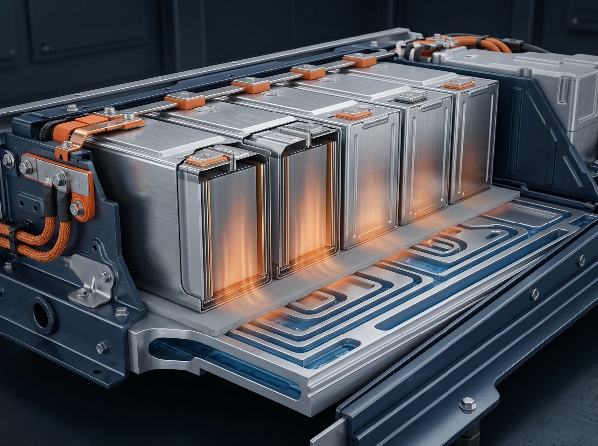
Why EV Battery Modules Need a Gap Filler
A lithium-ion cell never sits perfectly flush against its cooling plate. Tolerances in the cell height, the module frame, the cold plate flatness and the adhesive bonds that hold the stack together all accumulate into a gap that can range from fractions of a millimeter to several millimeters across a single module. Air is a terrible conductor — roughly 0.026 W/m·K — so wherever that air stays trapped, heat has to detour around it. The result is hot spots, uneven cell aging, and a pack that derates earlier than its design intended. Under fast charging, the same hot spots push cells closer to thermal runaway.
That is the job of a thermal gap filler: a dispensable, thermally conductive material that flows into the void between cells and the cooling plate (or between cells and the module housing), wets both surfaces, and carries heat out of the stack. It is one of the few components in the battery pack that you can tune independently of the cell chemistry, which makes it a favorite lever for thermal designers. This guide walks through how to select a gap filler for EV battery modules across seven decision dimensions, from thermal conductivity to qualification. For a full map of the material families used across packs, start with our EV battery thermal management materials guide.
Gap fillers earn their keep in three places in a pack: between individual cells in a cluster, between the cell cluster and the module housing, and between the module and the cooling plate. In cell-to-pack designs, the filler goes directly between the cells and the cold plate. Each location sees a different gap range, different surface roughness, and different mechanical loads — which is why the selection guide below treats them as separate inputs rather than one generic "battery" requirement. Thermally conductive gap fillers are also chosen partly for what they prevent: they fill air gaps that would otherwise concentrate heat, and they provide electrical insulation to the rest of the module, reducing the risk of short circuits and overheating that shorten battery life.
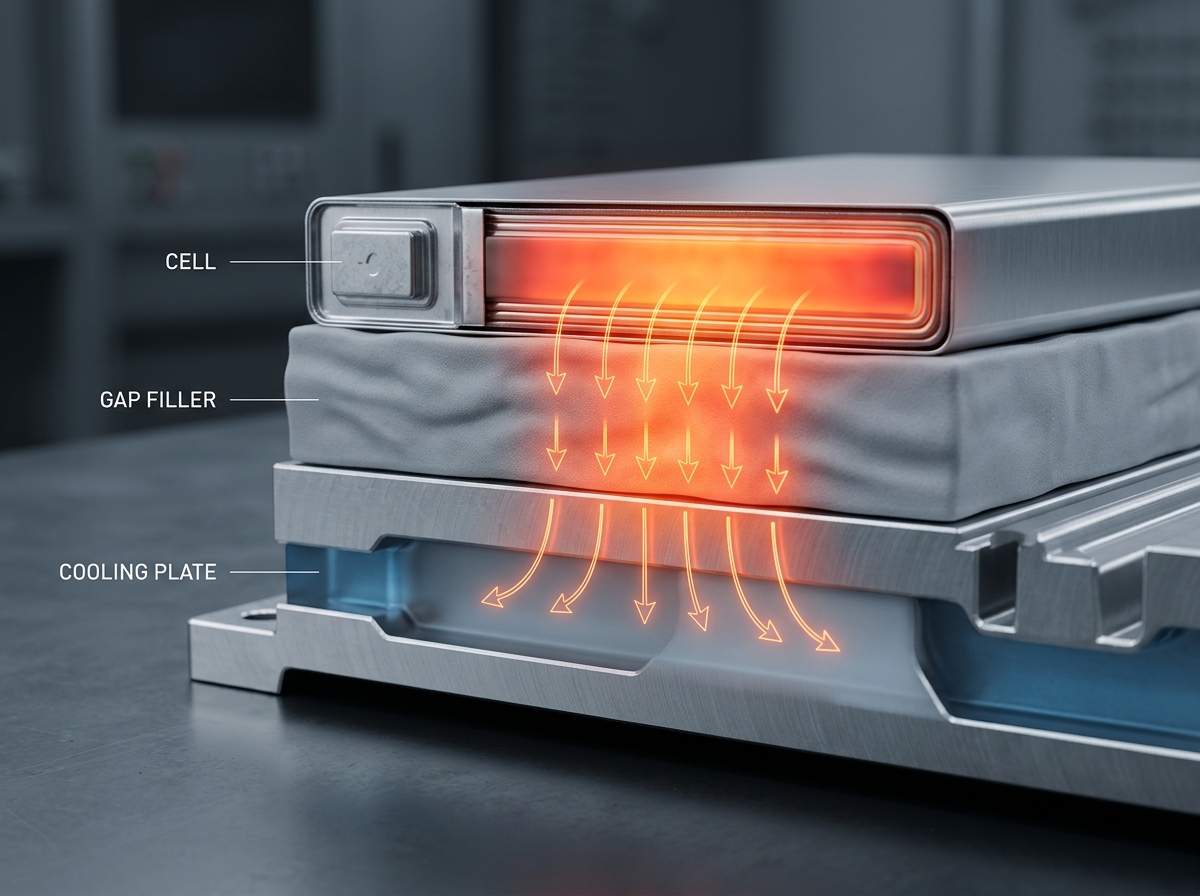
Heat generated by the cells passes through the gap filler layer into the cold plate; trapped air in the same path is the failure this material exists to prevent.
Gap Filler vs. Thermal Pad vs. Potting Compound
Before comparing products, decide which material class actually solves your problem. The three get mixed up constantly in specifications, but they answer different questions:
| Material | Best for | Key limits | Typical thermal conductivity |
|---|---|---|---|
| Thermal pad | Predictable gaps with tight tolerance control; simple manual assembly | Needs compression force; conforms poorly to rough or angled surfaces; thickness is fixed at die-cut | 1–16 W/m·K |
| Thermal gap filler (dispensable gel) | Variable or unknown gaps (roughly 0.5–5 mm), rough surfaces, low-stress assembly on fragile cells | Needs dispensing equipment; two-part versions add mixing and cure steps | 1.5–9 W/m·K |
| Potting / encapsulation compound | Fully encapsulating cells or modules against moisture, vibration and shock | Not optimized as a primary thermal interface to a cold plate; hard to rework | 0.6–4.5 W/m·K |
A thermal pad is a pre-formed solid sheet: it works when your tolerance stack is controlled well enough that the compressed pad stays in contact everywhere. A dispensable thermal gap filler is the answer when the gap varies — because of cell height tolerance, bowed surfaces, or assembly tolerances — because the liquid conforms to whatever it lands on before it cures. Potting compounds sit in a different category: they surround components to protect them, and while they are thermally conductive, they are not the right tool for making a controlled thermal interface to a cold plate. Our gap filler vs gap pad vs phase-change comparison walks through the adjacent alternatives in more depth.
One more distinction worth naming: as an E-Mobility Engineering review of battery thermal barriers notes, thermally conductive gap fillers reduce material waste and extend pack life — but the same review is blunt about the trade-off: cured silicone fillers can bond components so thoroughly that disassembly means discarding the module whole, a growing regulatory consideration in Europe and North America. The bottom line on form: the gap filler vs thermal pad decision comes down to how well you can control the gap, not which material has the nicer datasheet.
Thermal Conductivity: Match It to the System, Not the Datasheet
The first spec everyone reaches for is W/m·K, and it is also the most misused one. A higher thermal conductivity number does not automatically mean a cooler battery, because the total thermal resistance of the interface is the sum of the material's resistance and the contact resistance at both surfaces. A gap filler's real advantage is that it wets the surfaces and eliminates those air voids, so a 1.7 W/m·K gel with a thin, fully-wetted bondline can outperform a 6 W/m·K pad bridging the same gap with partial contact. As a thermomechanical simulation study of EV battery pack gap fillers shows, gap fillers beat pads on thermal impedance precisely because they conform to surface roughness before curing.
In practice, most EV module thermal designs land between 1.5 and 5 W/m·K. Henkel's 2026 launch of the Bergquist TGF 2030APS, a silicone-free two-component thermal gap filler aimed at cell stacks, specifies just 1.7 W/m·K — enough for the cell-to-cooling-plate path in high-volume production. At the high end, two-part cure-in-place materials like Laird's Tflex CR607 reach 6.4 W/m·K for designs that need maximum conductivity and can absorb the cost. As a middle example, our TIF035-05AB two-component thermal gel carries 3.5 W/m·K with a thermal impedance of 0.080 °C·in²/W at 10 psi — the grade most often specified for cell-to-cold-plate interfaces in our customer programs.
When you evaluate datasheets, ask for the thermal impedance value and the test conditions, not just the conductivity. Impedance is what the system actually feels, and it depends on bondline thickness, pressure and surface finish. If you need a refresher on how thermal conductivity is measured and reported, our W/m·K explainer covers the test methods.
Gap Size, Compression and Cell Expansion
Walk the assembly line with a feeler gauge and a tolerance study before you pick a material. In a typical prismatic module, the gap between cells and cold plate spans roughly 0.5–5 mm once all tolerances stack up, and it is rarely uniform. This range is exactly where dispensable gap fillers shine and pre-cut pads struggle: a 2 mm pad cannot fill a 4 mm pocket without massive compression, and a 4 mm pad leaves a 0.5 mm region over-compressed.
Compression force is the second half of this dimension. Battery cells are fragile: excessive assembly pressure can crack or distort them, and pressure on the cell face during fast charge is a known failure contributor. A liquid gap filler applies near-zero force during dispensing — the material is pumped in, not pressed in — which is why low-compression application is a headline benefit of every major supplier's material, and why OEMs pair gap fillers with lightweight module housings. The practical limit is compression ratio: a cured gel that can be compressed beyond 50% of its relaxed thickness fills a 0.5–5 mm void without stressing the stack.
The EV-specific twist that most selection articles miss is cell expansion. Prismatic cells swell and contract with state of charge and with age — by up to several percent of thickness over life. A gap filler must stay compliant through thousands of charge–discharge cycles, following the cell face as it moves, or the interface degrades and thermal impedance creeps up. Soft cured gels with low hardness (Shore 00 in the 20–40 range) handle this; hard, highly-filled pads do not, and can even pump stress back into the cell. In one cell-to-pack program, replacing pre-cut pads with a ZIITEK TIF thermal gel at over 50% compression ratio filled the full 0.5–5 mm gap envelope and passed the OEM's vibration and aging tests — a combination a pad stack could not match. For the pad-side view of this trade-off, our thermal pad thickness and compression guide explains how pads handle their own gap ranges.
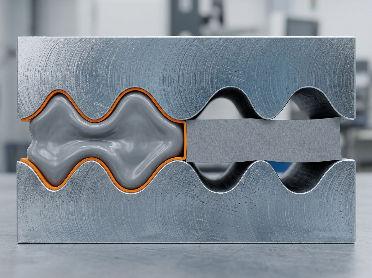
A liquid gap filler wets and fills a variable-height gap; a rigid pad bridges it, leaving air pockets where the surfaces pull away.
One-Part or Two-Part: Choose the Form That Fits Your Line
The biggest process decision in a gap filler specification is the material form, because it dictates what your dispensing line looks like.
One-component, non-curing gap fillers are paste-like materials that are dispensed and left as-is. They never cure, so they stay soft and remain removable — useful for serviceability and recycling. There is no mixing, no ratio control, no pot life to watch, and no cure oven. The trade-off: they do not hold position on their own, so a module relying on the filler for structural stabilization during vibration needs mechanical retention elsewhere. Suppliers design these pastes for low oil separation, which keeps silicone oils from migrating onto cell contacts over time.
Two-component (2K) curing gap fillers mix on the line and cure in place into a soft elastomer. They lock the assembly together — useful when the module sees hard vibration — and their viscosity can be tuned for fast injection. The costs are process ones: you need a meter-mix system holding the mixing ratio, you manage pot life on the dispense side, and cure time becomes part of your cycle-time budget. A two component thermal gap filler is the dominant choice for cell-to-cold-plate paths in high-volume packs precisely because cured elastomers combine conductivity, compliance and position-holding in one layer.
| Decision | One-part (non-curing) | Two-part (curing) |
|---|---|---|
| Mixing on line | None | Meter-mix, ratio controlled |
| Cure step | None | Room-temperature or heat-accelerated |
| Holds position under vibration | No — needs mechanical retention | Yes, after cure |
| Rework / recycling | Easy to remove | Depends on bond strength (see below) |
| Typical throughput | Very high — dispense and go | High, but pot life and cure must be managed |
Dispense rate matters at pack scale: modern 2K materials are specified to dispense at over 40 cc/sec, so a module's gap-filling step takes seconds, not minutes. If your volume is low or your line is manual, the simpler one-part route often wins on total cost even with a lower price per kilogram on the two-part material — the equipment investment is where the money actually goes.
Cure, Adhesion and the Silicone Trade-Off
Cure behavior sets your cycle time. Two-part silicones cure at room temperature in minutes to hours depending on the formulation, and heat accelerates the reaction when the line can afford an oven pass. Room-temperature cure is attractive not just for cost but for energy: Henkel positions the room-temperature-curing TGF 2030APS partly as an energy-saving process choice for high-volume assembly. Whatever you pick, verify the cure schedule against your takt time — a material that needs 24 hours to full cure will quietly dominate your work-in-process.
Adhesion is a double-edged sword. A two-part gap filler with real bond strength keeps the module stack in position through vibration and vehicle-level shock — the silyl-modified-polymer systems used in battery packs cure into a network that holds components in place and keeps building durability over the pack's life. But strong adhesion is the enemy of serviceability: when a pack is opened for repair or recycling, a bonded layer that refuses to release forces the module to be scrapped whole. This is why material selection should explicitly state your rework policy — low-bond-strength formulations exist precisely so modules can be disassembled down to reusable parts.
The silicone question deserves its own paragraph, because it polarizes EV specifications. Silicone thermal gap fillers dominate the market: they offer thermal stability, easy dispensing and wide operating ranges. The catch is low-molecular-weight siloxanes. In sensitive electronics they can outgas and migrate over time, depositing on electrical contacts and degrading connectivity — the reason many OEMs now ask for silicone-free options. As Bostik's guide to silicone-free thermally conductive gap fillers explains, non-silicone formulations based on silyl-modified polymers avoid the migration issue entirely while still curing into a compliant elastomer, and they maintain performance at operating temperatures up to 150 °C. If your module has exposed connectors, cell voltage-sense boards, or a history of contact-resistance failures, treat "silicone vs silicone-free" as a real requirement, not a chemistry footnote. Where outgassing is the specific concern, look for low-volatile-siloxane grades or explicitly non-silicone formulations.
Dielectric Strength and 800V Voltage Isolation
Battery platforms are moving from 400 V to 800 V, and the gap filler often sits exactly where the insulation margin is needed: between cells and the cooling plate, or between the cell cluster and the module housing. Because gap fillers are expected to provide electrical insulation to the rest of the module, dielectric strength is a first-class selection criterion, not a bonus checkbox.
The physics is thickness-dependent. Withstand voltage scales with bondline thickness, so the same material that gives you comfortable margin at a 3 mm gap may be marginal at 0.5 mm. That creates a genuine trade-off: thicker bondlines improve both dielectric margin and tolerance absorption, but raise thermal impedance. Your requirement should therefore be written as a withstand-voltage target at the minimum bondline the tolerance study allows, not at the nominal thickness.
There is a subtler coupling to watch: raising thermal conductivity usually means loading more ceramic filler, and aggressive filler loading can erode dielectric margins and make the cured material harder. The right approach is to specify both numbers — thermal impedance and withstand voltage at min bondline — and require the supplier to test both on the same sample geometry. Also check the material's behavior at temperature: dielectric strength is specified at operating temperature in automotive qualification, because both conductivity and breakdown voltage shift when the pack is hot.
Application Process, Equipment and Cost
A gap filler only helps if the line can apply it repeatably. The three process pillars are pattern, flow and mixing.
Pattern. Modules are typically filled with continuous beads laid in a serpentine or grid pattern, or sprayed, depending on the surface area and the gap shape. The pattern must cover the cell face without trapping air pockets — a bead spacing that is too wide leaves unfilled regions that defeat the entire purpose.
Flow. Dispense rate is a throughput number: at 40+ cc/sec, a full module face is covered in seconds, which is how gap fillers stay compatible with automotive cycle times. But fast flow plus abrasive filler is hard on equipment. Traditional high-conductivity gap fillers are loaded with aluminium oxide, which sits at 9 on the Mohs hardness scale — like pumping fine sandpaper through your valves and pumps. Alternative fillers such as aluminium trihydroxide (Mohs 3) flow through dispensing equipment with far less abrasion, cutting maintenance downtime at the cost of some conductivity headroom.
Mixing. Two-part systems live or die on ratio control. A 1:1 or 2:1 ratio that drifts by a few percent changes both conductivity and cure behavior, so the meter-mix unit — static mixer quality, shot-to-shot repeatability, purge cycles between shifts — is part of the material spec. Budget the pot life carefully: if the line stops longer than the pot life, the mixer and nozzle purge before restart is real scrap.
Then there is the cost argument that decides most programs. Dispensable gap fillers eliminate the pad value chain: no die-cut blanks, no pad inventory across thicknesses, no manual placement, no pressure-sensitive adhesive to misalign. In the same cell-to-pack program mentioned earlier, the switch from pre-cut pads to a dispensable thermal gel cut material cost by about a third. Automation also removes a manual step from the line, which is why the shift to gap fillers usually coincides with a shift toward automated module assembly. If you are evaluating the change, model total applied cost — material, equipment depreciation, scrap, and labor — rather than comparing price per kilogram. A walk through our thermal gel range shows the one-part and two-part TIF series grades available for these trade-offs.

Automated bead application keeps gap-filler coverage repeatable at automotive production rates.
Qualification and Testing to Demand
Automotive battery programs fail on unverified materials, not uncompetitive ones. Before you commit a gap filler to a module design, demand evidence on each of these:
| Evidence to demand | Why it matters | What to check |
|---|---|---|
| Thermal impedance with its test method | W/m·K alone says nothing about the interface's real resistance | Require ASTM D5470 data, reported with applied pressure, bondline thickness and test temperature |
| Vibration and thermal aging | The module sees years of road vibration and thermal cycling | Ask which automotive standard the data follows (our TIF gel program passed LV124-class vibration combined with 125 °C / 1,000-hour thermal aging), and whether tests ran on the material alone or a module coupon |
| Flammability | Pack-level fire safety requirements are non-negotiable | Confirm UL94 V-0 applies at the thickness you plan to use — ratings can change with thickness |
| Dielectric withstand | Your isolation margin depends on it (see the section above) | Require the value at minimum bondline and operating temperature |
| Outgassing | Sensitive contacts degrade if volatiles migrate | Look for total mass loss / collected volatile condensable material data |
| Quality system | Automotive supply chains audit their material suppliers | Confirm IATF 16949 sites, material traceability, batch records and PPAP-style documentation |
| Shelf life and pot life | Purchasing and production need them to plan | Demand both, stated on the datasheet |
Then validate on your own hardware. A sample validation plan costs little and catches most surprises: dispense coupons at your real gap and cure schedule, measure bondline thickness, thermal impedance, adhesion and dielectric strength after cure, and run a vibration test on a short module stack. The full pack-level picture — including how the filler interacts with your busbars, sensors and seals — belongs in our EV battery pack thermal management overview, which covers the surrounding materials in the same pack.
A Six-Step Checklist Before You Specify
- Map the gaps. Measure the min–max gap envelope across your tolerance stack — cell-to-cell, cell-to-module, module-to-cold-plate — and note surface roughness at each interface.
- Set the thermal budget in impedance, not W/m·K. Write the target thermal impedance and the bondline it applies to.
- Choose the form for your line. One-part if you want no mixing and easy rework; two-part if you need position-holding and cured compliance — then verify dispense rate against your takt time.
- Fix the cure, adhesion and silicone policy. Room-temperature vs. accelerated cure, bond strength vs. reworkability, and silicone vs. silicone-free based on your contact-sensitivity.
- Verify dielectric for your platform. Withstand voltage at minimum bondline and operating temperature for your 400 V or 800 V architecture.
- Demand qualification data, then run your own. ASTM D5470 impedance, automotive vibration and aging, UL94 V-0, outgassing, IATF 16949 — and a coupon-level validation on your own line.
Getting the selection right on paper is half the work; the other half is a supplier that ships consistent material and answers questions with data. ZIITEK's thermal engineers work through this exact checklist on EV programs — if you want a second pair of eyes on your spec, or samples to run your own validation, contact our thermal team with your gap envelope and thermal budget and we will take it from there.