Heated Optical Window: ITO Heated Glass Guide
ITO heated glass clears fog and frost on optical windows when power density holds the surface above its dew point; here is the arithmetic to size the window.
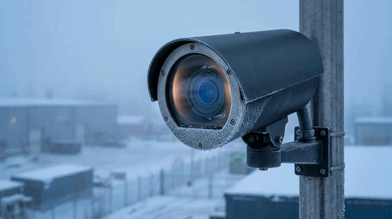
What ITO Heated Glass Has to Beat: Fog, Frost and the Dew Point
A heated optical window is not specified by temperature, although nearly every catalogue page sells it that way. Two numbers decide whether the window stays clear: the dew point of the air it faces, and how far above that dew point its inner surface sits. Get the margin and the window is clear at any ambient temperature. Miss it and no amount of watts helps, because the surface condenses whenever it is the coldest thing in the enclosure.
The construction itself is simple. ITO, indium tin oxide, is a transparent conductive oxide sputtered onto glass in a layer a few hundred nanometers thick. Busbars at two edges connect the film to a supply; current spreads across the aperture and the film's sheet resistance turns it into heat. There are no visible wires, no grid lines in the image, and nothing to clean around — which is why the construction dominates camera windows, sensor covers and instrument glazing rather than, say, rear windows.
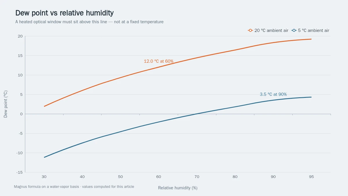
Condensation physics is where the specification actually starts. Air at a given temperature holds a fixed maximum of water vapor; cool a surface below the temperature at which that air is saturated and water deposits on it. The National Weather Service glossary defines that saturation temperature as the dew point, and it is computable from dry-bulb temperature and relative humidity with the Magnus form most weather services use:
γ = ln(RH/100) + 17.62·T / (243.12 + T), then Td = 243.12·γ / (17.62 − γ), with T in °C.
The requirement is run against a surface target of the dew point plus 3 K — the margin a condensation model needs above the deposition threshold. Against an unheated pane that runs 5 K below the air, three cases fall out:
| Ambient air | RH | Dew point | Unheated glass (assumed air − 5 K) | Lift to hold Td + 3 K |
|---|---|---|---|---|
| 20 °C | 60% | 12.0 °C | 15.0 °C | 0.0 K |
| 5 °C | 85% | 2.7 °C | 0.0 °C | 5.7 K |
| −10 °C | 80% | −12.8 °C | −15.0 °C | 5.2 K |
The last column is what a heater is actually buying, and it is usually skipped. At 20 °C and 60% RH the dew point sits 8 K below ambient — below even the air − 5 K pane assumed in the table — so that case needs no heat at all. The cases that matter are cold and damp, and in those the requirement is a lift of roughly 5–8 K above the unheated pane, not a target temperature and not 20 K. The 5 K offset in the table is an assumption, not a constant: a pane that sees clear sky radiates to it and settles several kelvin below air temperature, and a housing that conducts to a cold body drags the glass further. Measure the unheated pane in the application, then add the margin.
Take 8 K as the minimum design lift: the computed requirement at these cases is 5.2–5.7 K, and the rest of the margin absorbs wind, the unheated border and a colder mounting. Take 20 K for a window that has to clear in seconds. The two sections that follow use both.
Frost is the other duty. Below 0 °C, water vapor deposits directly as ice, and a surface held a few kelvin above the dew point is still below freezing: it stays clear of deposition, but ice already on the pane — or snow driven onto it — has to be melted, and an anti-fog window specified for margin alone has no budget for that. Melting costs latent heat on top of everything else, roughly 334 J per gram. The energy budget below turns that into seconds. The practical consequence is that "defog" and "defrost" must be specified as two requirements with two power levels, not one.
This article is one spoke of the heating film elements hub, which indexes the other constructions — film heaters, pads and glass — for readers whose aperture is not optical.
Sheet Resistance, Busbar Geometry and the Voltage You Actually Need
Three equations carry the electrical design of a heated optical window:
- R = Rs × L / W — heater resistance from the film's sheet resistance and the geometry between the busbars.
- P = V² / R — power from the supply you have.
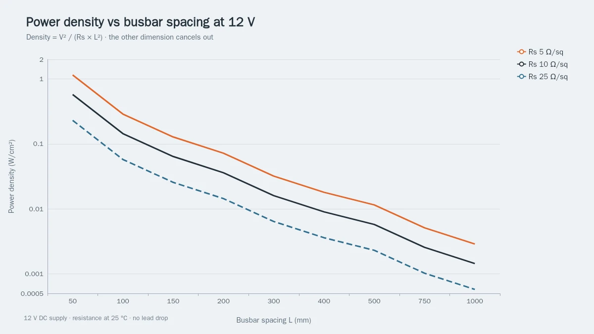
- Density = P / (L × W), which collapses to V² / (Rs × L²).
Sheet resistance, in ohms per square (Ω/sq), is the resistance of any square of the film regardless of its size — the property a coating house sells. L is the distance between the busbars; W is the busbar length. Because a square of film has the same resistance whatever its size, R scales with the aspect ratio only, and the last equation shows something most catalogue tables hide: power density depends on the supply, the coating and the busbar spacing — and on nothing else. Not on the other dimension of the window, not on its area.
| Window (mm) | Rs (Ω/sq) | R | Supply | Power · density |
|---|---|---|---|---|
| 100 × 100 | 10 | 10 Ω | 12 V DC | 14.4 W · 0.144 W/cm² |
| 100 × 100 | 10 | 10 Ω | 24 V DC | 57.6 W · 0.576 W/cm² |
| 100 × 100 | 10 | 10 Ω | 5 V DC | 2.5 W · 0.025 W/cm² |
| 200 × 100, busbars on the long edges | 10 | 5 Ω | 12 V DC | 28.8 W · 0.144 W/cm² |
| 500 × 500 | 10 | 10 Ω | 12 V DC | 14.4 W · 0.006 W/cm² |
| 500 × 500 | 3 | 3 Ω | 36 V DC | 432 W · 0.173 W/cm² |
Rows four and five are the ones worth staring at. Doubling the window to 200 × 100 mm doubles the power (28.8 W) but leaves the density untouched at 0.144 W/cm², because the busbar spacing stayed at 100 mm — the current simply doubled to 2.4 A. Half a meter square is enough to see the problem: the same 10 Ω/sq coating on a 500 × 500 mm pane at 12 V collapses to 0.006 W/cm² — twenty-five times too little to clear anything: the busbar spacing grew with the pane, and density falls with its square.
Row three is easy to misread. A 5 V supply on the same 100 mm pane gives 2.5 W, which settles about 10 K above ambient in still air — but a 56 J/K pane losing 0.24 W/K has a time constant of 234 s, so three minutes buys about 6 K and an 8 K lift takes roughly six minutes once losses are counted (180 s with none). That is enough for a small aperture that can wait, and not enough once wind and a cold border are counted — a narrower job, not a broken design.
That is why the 1.5–36 V range exists as a product range rather than a single number. Those are the rails this class of window is driven from — 5 V from logic and USB supplies, 12 V and 24 V from vehicle and industrial systems, and up to 36 V where the coating and the busbar spacing demand it — and the coating and geometry have to be chosen to land the density you need on the rail you have. Two levers move it at fixed voltage: lower sheet resistance (more conductive coating, at an optical cost) or shorter busbar spacing (a third busbar down the middle of a 500 mm pane halves L and multiplies density by four at Rs 10 — the same pane then runs at 0.023 W/cm² instead of 0.006; two more internal busbars quarter L and multiply it by sixteen).
ZIITEK publishes its Kheat® ITO glass at 1.5–36 V with transmittance of at least 90%, or 95% with an AR coating — a range that covers small camera apertures up to architectural panes, with the coating and busbar layout selected per drawing. The sheet-resistance option, uniformity and current at the rail you choose are confirmed at quote, because they follow from the geometry rather than being catalogue constants.
Assumptions behind every row above: resistance measured at 25 °C, ideal supply, no lead drop, uniform film. Real builds lose a few percent in the leads and a few percent in the film's temperature drift; both are worth measuring at the heater rather than trusting the supply setting.
What the Coating Costs in Light: Transmittance, Haze and Reflection
Two figures a buyer of a heated optical window sees on every page in this category are "≥90% transmittance" and "≥95% with AR", and they are not comparable until three things are stated: the wavelength band, whether the substrate is included, and whether the window is laminated. A supplier quoting ">85% at 550 nm" for unlaminated glass and another quoting "up to 94%" for an index-matched laminated assembly are describing different objects — including, at the top of that range, index-matched ITO (IMITO), where the coating is matched to the glass index rather than to air.
The number is a luminous transmittance measured through the finished aperture — ITO plus glass, or ITO plus glass plus interlayer plus a cover pane. A bare ITO film absorbs a few percent in the visible, so a single-layer coating on thin glass typically lands in the high 80s. Pushing past 90% needs an antireflective stack on one or both faces; 95% needs it on both, and the stack has to be designed for the band you actually image in — visible, NIR or SWIR — not for 550 nm by default.
Conductivity and transmission pull against each other. A thicker ITO layer lowers sheet resistance and raises absorption, so coating suppliers sell a ladder of sheet resistances, from a few ohms per square up to the kilo-ohm range (PGO publishes 3.5 Ω/□ to 1 kΩ/□ across its ITO series). For a heater the ladder matters directly: at fixed voltage and geometry, going from 10 Ω/sq to 100 Ω/sq cuts power density by ten. Which is why the optical requirement and the electrical one have to be negotiated in the same conversation — a transmission target that forces a high-resistance coating also forces a higher supply or a shorter busbar spacing.
Haze is the second optical cost, and the one that actually shows up in an image. ASTM D1003, the haze and luminous transmittance method written for transparent plastics, is the test most suppliers quote for coated windows; it reports the fraction of transmitted light scattered outside a small cone. A clean sputtered ITO layer scatters very little. The haze that matters arrives later — from the AR stack's microstructure, from abrasion, from a laminating interlayer, or from condensation itself.
The third cost is reflection. An uncoated glass face reflects about 4% per surface, and inside a camera housing that reflected light can ghost across the sensor. AR coating is therefore doing double duty: it recovers the transmittance the ITO took away, and it suppresses the internal reflection that hurts contrast. State the reflection target with the transmission target, and say whether it applies to the coated face, the outer face or both.
Where Hot Spots Come From: Busbars, Edges and Laminations
A heater that averages the right power density can still fail, because the failure is local. Four mechanisms account for most of it.
Current crowding at the busbar. Current enters along one edge and leaves along the other; near the terminations the current density is highest, and contact resistance between the busbar and the ITO adds a local step. A silver frit busbar, a silver-epoxy busbar and a sputtered Cr/Ni/Au pad have different contact resistance and different tolerance for solder versus conductive adhesive. The design consequence is simple: keep the termination outside the clear aperture, and treat the last few millimeters near each pad as a hotter zone.
The unheated border. The coating stops at the busbar, and the seal or frit occupies a few millimeters beyond it. That border runs colder than the aperture, so it is the first place condensation appears — a fogging ring at the edge of an otherwise clear window, which reads to a user as a product failure. Specify the heated area separately from the clear aperture, and check that the border still lands above the dew point.
Buried versus accessible ITO. In an accessible construction the coating is the top layer and can be contacted directly; in a buried construction it sits under dielectric layers, which buys abrasion and environmental durability but requires masking or etching to reach the film. Both are legitimate; the mistake is specifying a durability requirement without saying which construction you expect, because the two have different edge seals and different rework paths.
The lamination and the lead exit. In a laminated window the interlayer is the moisture path and the lead exit is the weak point. Thermal cycling pumps the bond line; a void at the exit becomes a delamination front, and a delamination front becomes a hot spot, because the heat that used to spread into the cover pane now stays in the film. This is the mechanism behind most field failures that get reported as "the heater burned out".
Two rules of thumb when you set the uniformity requirement for a heated optical window, both of them arithmetic rather than folklore. A sputter process holds sheet resistance to within a few percent across a pane — take ±3%. Resistance tolerance becomes power tolerance, so ±3% of power is about ±0.24 K at the 8 K design lift and about ±2 K on a surface running 60 K above ambient: uniformity matters at the top of the power range and barely at the bottom. The second rule: borders and terminations are outside that number, because the coating geometry there differs from the aperture.
The interface between the film, the glass and any bonded cover is where thermal resistance accumulates; if that layer is part of the design, the thermal resistance versus impedance explainer covers how to state it so it can be compared across suppliers.
Thermal Inertia: Time-to-Clear Is an Energy Budget
Power density tells you whether a heated optical window can be held clear. It does not tell you how long that takes, and for a camera that must see within thirty seconds of power-up, the second question is the one that decides the design.
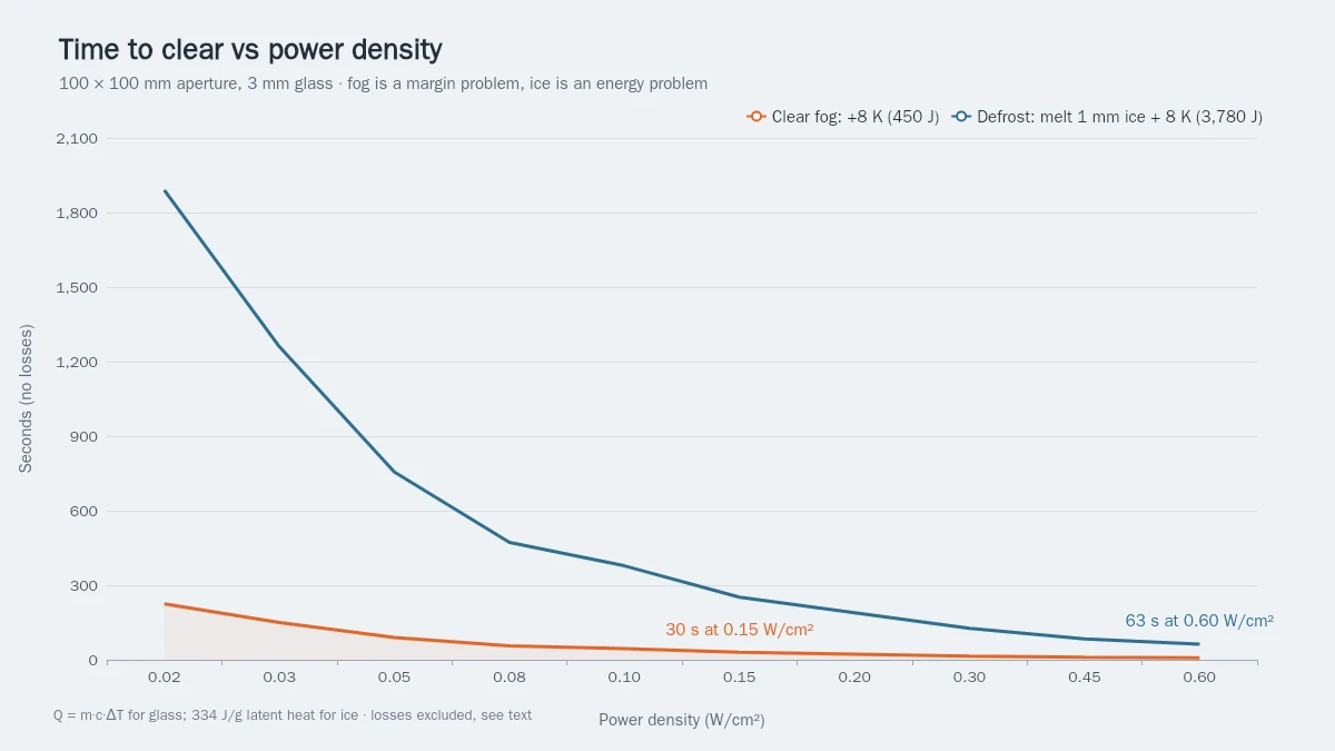
The heat-up energy for the glass itself is Q = m · c · ΔT. Take a 3 mm pane, 100 × 100 mm: 30 cm³ of glass, about 75 g at 2.5 g/cm³, with a specific heat near 0.75 J/(g·K). That is 56 J per kelvin — 450 J for the 8 K design lift, 1,125 J for a 20 K fast clear. Divide by the power you have:
| Duty | Energy | 2.5 W | 14.4 W | 57.6 W |
|---|---|---|---|---|
| Clear fog: +8 K on a cold pane | 450 J | 180 s | 31 s | 8 s |
| Fast clear: +20 K | 1,125 J | 450 s | 78 s | 20 s |
| Defrost: melt 1 mm ice, then +8 K | 3,780 J | 1,512 s | 263 s | 66 s |
Losses are not optional, and the coefficient has to be stated per face. A vertical pane in still air sheds heat at roughly 12 W/(m²·K) per face, and a window has two faces — so a 0.01 m² aperture sheds at about 0.24 W per kelvin. On that basis 2.5 W settles near 10 K above ambient, 14.4 W near 60 K, and 57.6 W near 240 K. Moving air at 20 W/(m²·K) per face raises the coefficient by two-thirds, to 0.4 W/K, and pulls those figures down to about 6 K, 36 K and 144 K.
Ice is where the budget changes character. One millimeter of ice over the same 0.01 m² is about 10 cm³, or 9.2 g at 0.917 g/cm³. Melting it takes 334 J/g — about 3,063 J — plus roughly 270 J to warm the ice and the meltwater. Add the pane's own 450 J for the 8 K lift and the full defrost duty is about 3,780 J, eight times the fog duty at the same lift. That is why a window specified only for fog can look generous in still air and still fail its first freezing morning.
Thickness compounds it. A 6 mm pane doubles the mass to 150 g and therefore doubles the heat-up energy; a thicker pane also spreads heat better, which improves uniformity. Both effects are real, and both belong in the specification rather than in the supplier's defaults.
Vehicle glazing is the case where this becomes a regulated number rather than a design preference. In the United States, FMVSS 103 sets windshield defrosting and defogging performance for the vehicle as a whole, with time-based criteria under defined ambient conditions. A component specification cannot inherit that pass, but it can and should be derived from it: translate the vehicle-level time criterion into a surface-temperature-versus-time curve for your aperture, then size power density against that curve. The same logic transfers to camera housings, where the "criterion" is the seconds your system allows before first usable frame. The arithmetic is the same shape as the battery heating film problem, where the pack has a mass, a target rise and a power budget too.
ITO Versus Fine Wire, CNT and Metal Mesh
ITO is not the only way to make transparent heated glass, and the choice is decided by four trade-offs rather than by preference.
| Construction | Sheet resistance | Wins on | Costs you | Fits |
|---|---|---|---|---|
| Sputtered ITO | 3.5 Ω/sq to the kilo-ohm range, selected per build | optical uniformity, no visible pattern, EMI shielding as a by-product | brittle coating, size limited by the sputter chamber, needs busbars | camera and sensor windows, instrument glazing, displays |
| Fine wire (tungsten) | very low, set by wire spacing | large area, low cost, mechanically tough | visible lines, obstruction in the image, haze | vehicle backlights, large non-imaging panes |
| Carbon nanotube film | higher, coating-dependent | flexibility, bend tolerance | higher resistance for the same transmission, less mature supply base | curved and flexible apertures |
| Metal mesh | low, set by mesh pitch | conductivity at large size, bend tolerance | moiré against sensor pixel grids, visible pattern close up | large touch and antenna surfaces, displays |
The decisive question is usually the aperture size and the imaging requirement together. A 20 mm camera window with a 5 Ω/sq coating and 1.5 V across it lands at about 0.11 W/cm² — workable, because the busbar spacing is only 20 mm and the density equation rewards that. The same coating on a one-meter architectural pane at any sensible voltage produces almost nothing; that pane wants a low-resistance coating, closer busbar spacing, or a different construction entirely. When the surface to be heated is not optical — a plate, a housing wall, a pipe — a film or pad heater is usually the cheaper answer, which is what the polyimide heating film and silicone rubber heater pads guides cover.
Bend radius deserves its own line. Sputtered ITO is a ceramic: it tolerates a gentle cylindrical form when the bend axis and the busbar geometry are designed together, and it cracks when bent sharply or repeatedly. If the aperture is genuinely flexible or has to survive flexing in service, the coating is the wrong family and a film heater on a flexible substrate is the right one — an honest limitation to settle before tooling.
EMI is the free extra. A conductive transparent layer shields as well as heats, and in a housing with a digital sensor that can remove a separate mesh window from the bill of materials. It is a by-product of the same film, not a separate feature, but it does need to be stated as a requirement so the sheet resistance and the grounding path are chosen for it.
Control and Protection: Why an Uncontrolled Heater Cracks Glass
An ITO heater connected straight to a supply is a thermal runaway waiting for a fault. The density arithmetic above makes the case: at 0.576 W/cm² on a 100 mm pane, the surface would chase a steady-state rise of roughly 240 K over ambient with still-air losses, and no laminated assembly, no interlayer and no seal survives that. The heater is not dangerous because it is powerful; it is dangerous because its power density is nearly independent of temperature. Nothing in the film throttles it.
So the control loop is part of the component, not an accessory:
- Sense where the requirement lives. An NTC bonded to the glass near the aperture reads the surface the dew point margin is defined on. A sensor in the housing air reads something else, and controlling on it means the glass runs colder than the loop believes.
- Close the loop, do not switch it. A PID loop on a solid-state relay or a PWM driver holds the surface at the margin; a thermostat swings tens of kelvin around the setpoint, which is exactly the cycling that fatigues the bond line.
- Hard-wire an over-temperature cut-out. Independent of the controller and of the firmware, sized below the laminate's limit. A failed relay must not be able to run the heater to its maximum.
- Measure power at temperature. ITO resistance is temperature-dependent, so the current at −20 °C is not the current on the 25 °C drawing. Specify the power at the operating temperature and verify it there; otherwise the first cold morning is the first time anyone sees the real number.
- Size for the hot end. ITO's temperature coefficient is small — a few tenths of a percent per kelvin — and its sign depends on the deposition and anneal, so the film can draw slightly more current hot or cold. State the current at the top of the operating range, verify the cold-start current on hardware, and let the over-temperature cut-out, not the film's own behavior, be what bounds the hot case.
Cracking has a second route that control cannot fix: differential stress. A hot aperture inside a cold frame, or a hot spot beside a large unheated border, puts the glass in a temperature gradient. Annealed soda-lime glass tolerates a much smaller differential than tempered glass, and the tolerable figure depends on the pane, the edge finish and the mounting — which is why it belongs in the supplier's design review with the actual drawing, not in a rule of thumb borrowed from another project. Where the gradient cannot be designed out, tempering or a different mounting is the answer.
The Specification Sheet for a Heated Optical Window
Everything above collapses into a page you can attach to a drawing. Whether the part is a heated camera window, an instrument sight glass or an architectural pane, the fields are the same; send them and a supplier can quote a design rather than a guess.
| Field | What to state |
|---|---|
| Clear aperture and outline | dimensions, corner radii, holes, edge finish |
| Heated area | the coated region, stated separately from the aperture |
| Duty | defog only, defrost only, or both, with the ambient and humidity case for each |
| Surface target | margin above the dew point at that case, plus the lift above the unheated pane |
| Time-to-clear | seconds to first usable image or to clear, and the starting condition |
| Supply | voltage, AC or DC, tolerance, available current |
| Power density | W/cm² at the operating temperature, average and maximum |
| Sheet resistance | target and tolerance, or the power/voltage pair that fixes it |
| Busbar and termination | material, position, spacing, lead length, connector |
| Optical | transmittance band and target, reflection target, haze limit, AR faces |
| Stack | substrate, thickness, lamination, interlayer, cover pane, coatings |
| Environment | operating and storage temperature, IP requirement, chemicals, cleaning |
| Control | NTC position, setpoint, hysteresis or PID, over-temperature cut-out |
| Qualification | the test list below, with acceptance limits agreed in writing |
The qualification list is the part buyers most often leave to the supplier, and the part that decides whether the window survives three winters. Nothing below is a number to copy from this article — the limits belong to your application and must be agreed with the supplier — but every item should appear:
| Test | Condition to state | What it proves |
|---|---|---|
| Power at temperature | measured at the low end of the operating range | the density you designed for actually exists when it is cold |
| Aperture uniformity | delta-T across the clear aperture at steady state | the border and the center behave the same |
| Thermal cycling | number of cycles, dwell times, supply on/off | the busbar, the bond line and the seal survive |
| Humidity and condensation | soak plus powered cycling | no delamination and no insulation loss |
| Salt fog or chemical exposure | per the environment the window sees | the coating and the seal hold up |
| Abrasion and adhesion | wiper, tape pull or taber, as applicable | the AR stack does not polish off |
| Ingress protection | IEC 60529 IP rating, tested assembled | the housing, not the glass, is the sealing path |
| Optical after test | transmittance and haze re-measured | the window still images after the environmental sequence |
If you are at sketch stage, five inputs start the conversation: aperture and heated area, the ambient and humidity case, the time-to-clear you need, the supply rail you have, and the optical band. ZIITEK's Kheat® ITO glass is built for exactly this specification route — 1.5–36 V, ≥90% transmittance (≥95% with AR), ultra-clear electronic-grade glass, with NTC control, AR and AF coatings as options, for outdoor security-camera windows and architectural window glazing. The sheet-resistance option, uniformity and cycling performance for a given drawing are confirmed at quote. Send the five inputs for a quotation, or start from the film heating element range if the geometry is still open.
This article is published by ZIITEK, which manufactures the glass described above. The equations, published limits and test methods in it apply to any sputtered-ITO heater; the build-specific numbers are the ones a quotation confirms.
FAQ
Can ITO heated glass clear ice, or only fog?
Both, but they are different budgets. Fog is a margin problem: hold the surface 5–8 K above the unheated pane and the dew point never gets near it, which the 0.144 W/cm² case does comfortably. Ice is an energy problem: melting 1 mm over a 100 mm aperture costs about 3,063 J of latent heat plus roughly 720 J to warm the ice, the meltwater and the glass — about 3,780 J in total, which takes roughly 263 s at 14.4 W and 66 s at 57.6 W before losses. Size for the ice case if ice is in the requirement.
What voltage do I need for a 100 mm camera window?
It depends on the coating, and the equation is V²/(Rs × L²) for power density. With a 10 Ω/sq coating and busbars on opposite edges (L = 100 mm), 12 V gives 0.144 W/cm² — a solid defog duty — and 24 V gives 0.576 W/cm², which is enough for de-icing only as a short duty — held continuously it is the uncontrolled steady state the control section above rules out, so at that density the control loop is part of the design. A fixed 5 V rail on the same window is a different calculation, covered below.
Does the heater degrade image quality?
Not if the optical requirements are specified with it. A heated optical window is a stack — coating, glass, interlayer, cover — and a single ITO layer costs a few percent of visible transmittance and leaves a bare window in the high 80s; AR coatings recover that and also suppress the internal reflection that causes ghosting in a camera housing. Haze is the figure to watch, because it is the one that softens the image — quote it with the band and the method, and re-measure it after the environmental tests.
Can I run a heated window from 5 V USB?
On a small aperture with a low-resistance coating, yes — and only there. Density scales with V², so dropping from 12 V to 5 V cuts power by a factor of about 5.8 at the same geometry: the 100 mm, 10 Ω/sq example falls to 0.025 W/cm², about 10 K of steady rise in still air, but the pane's 234 s time constant means roughly six minutes to an 8 K lift once losses are counted (180 s with none). Shrink the aperture instead and the same rail works: a 20 mm window with a 5 Ω/sq coating and 5 V across it lands at 1.25 W/cm² — about 5 W into a 4 cm² pane — because the busbar spacing is five times shorter and density scales with its square. That is a real load on a USB port, and at that density the uncontrolled steady-state rise runs to hundreds of kelvin, so it is a duty-cycled design under the control loop above, never a continuously energized one. Rail and coating have to be chosen together, and so do the duty cycle and the cut-out.
Why is my heated window uneven, or why did it crack?
Uneven heating in a heated optical window is usually geometry: current crowding at the terminations, an unheated border that runs cold, or a busbar layout that leaves a long path on one side. Cracking is usually thermal stress or control — a hot spot against a cold frame, or a heater with no independent over-temperature protection chasing a steady state far above what the laminate can take. Both are design-review items, not defects to be found in the field.