Thermal Resistance vs Thermal Impedance Explained
Thermal resistance (K/W) is steady-state; thermal impedance adds time or area — for a TIM it's °C·in²/W at a set thickness. How they differ and when each matters.
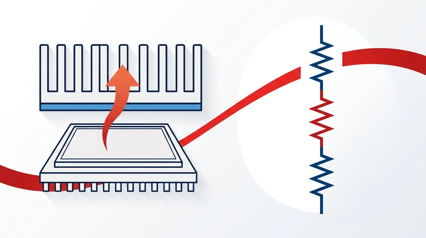
**Thermal resistance is a single steady-state number — the temperature rise per watt of heat flow, in K/W (or °C/W). Thermal impedance is the broader idea: it either (a) adds time to describe how a system heats up transiently, or (b), in thermal-interface-material datasheets, packages resistance and contact effects into an area-normalized value in °C·in²/W (or K·cm²/W) at a stated thickness and pressure.** They’re related but not interchangeable, and confusing them is one of the most common ways engineers mis-spec a cooling design.
This article defines both cleanly, shows the formulas and units readers keep searching for, and — the part that matters for material selection — explains which number you should actually compare when choosing a thermal interface material (TIM).
Quick comparison
| Thermal resistance (Rθ / R_th) | Thermal impedance (Z_th / θ) | |
|---|---|---|
| What it captures | Steady-state opposition to heat flow | Transient response (vs time) or area-normalized interface resistance |
| Typical symbol | Rθ, R_th | Z_th (transient), θ or Z (TIM datasheets) |
| Units | K/W or °C/W | K/W vs time (transient); °C·in²/W or K·cm²/W (TIM) |
| Depends on time? | No (equilibrium) | Transient form: yes |
| Depends on area? | Not normalized | TIM form: yes (per unit area) |
| Where you meet it | Heatsink specs, junction-to-case | TIM datasheets; transient/pulsed analysis |
What is thermal resistance?
Thermal resistance is the thermal analog of electrical resistance. It measures how much temperature difference builds up for a given rate of heat flow, at steady state:
Rθ = ΔT / Q
where ΔT is the temperature difference across the path (°C or K) and Q is the heat flow (W). The unit is K/W (equivalently °C/W). Lower is better — a lower Rθ means less temperature rise for the same power.
For a slab of material it follows directly from Fourier’s law of conduction: Rθ = L / (k · A), where L is thickness, k is thermal conductivity (W/mK), and A is area. Note what this says — a thicker bond line raises resistance; more area lowers it. That’s why bond line thickness is such a big lever in TIM performance (more on that in understanding thermal conductivity (W/mK)).
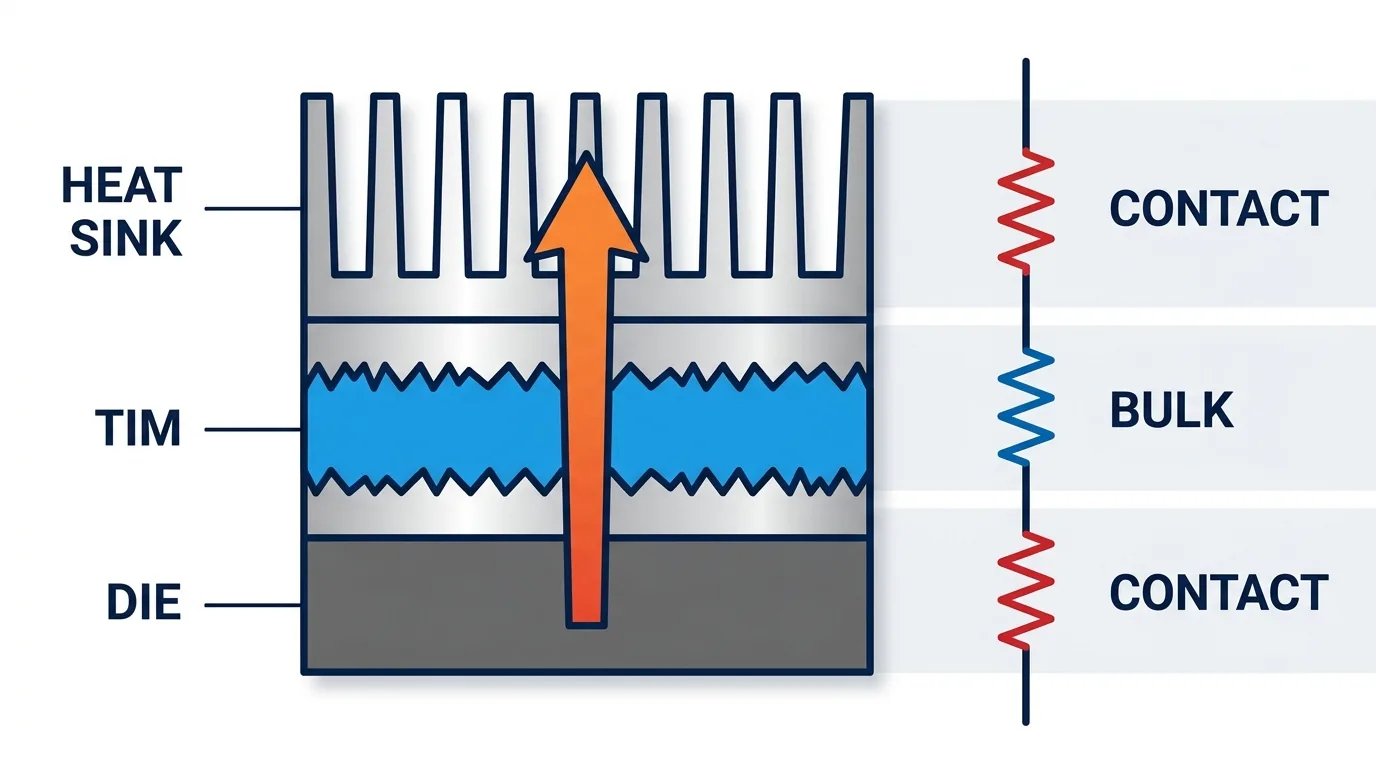
Real interfaces add one more term the slab formula ignores: thermal contact resistance at each surface, where microscopic roughness leaves the TIM imperfectly touching the metal. Total joint resistance = bulk resistance + the two contact resistances. A soft TIM that wets out reduces the contact terms — sometimes more than a higher-k material would.
What is thermal impedance?
“Thermal impedance” is used two ways, and the searcher’s confusion usually comes from meeting one definition while expecting the other.
1. Transient thermal impedance (Z_th). By analogy to electrical impedance, this describes the time-dependent thermal response. A real system has thermal mass (capacitance), so when you apply a power step the temperature doesn’t jump instantly — it rises along a curve. Z_th(t) captures that: at very short pulses it’s low (the mass hasn’t heated yet); as time goes on it climbs and asymptotes to the steady-state resistance. Power semiconductor datasheets publish Z_th curves (often modeled as RC “Cauer/Foster” networks, characterized per standards like JEDEC JESD51) so designers can predict junction temperature under pulsed or switching loads.
2. TIM datasheet “thermal impedance” (area-normalized resistance). This is the number you’ll see on a thermal pad or paste datasheet, in °C·in²/W or K·cm²/W. It’s the interface’s resistance multiplied by area — i.e., resistance per unit area — quoted at a specific thickness and clamping pressure. Normalizing by area lets you compare materials independent of part size, and folding in the test pressure makes it far more honest than bulk W/mK alone.
Thermal impedance vs thermal conductivity — the distinction that decides TIM choice
This is the practical crux, and a top reason readers land here. **Thermal conductivity (W/mK) is a bulk property of the material; thermal impedance is a property of the joint.** Conductivity ignores thickness, pressure, and contact resistance — impedance includes all three.
That’s why a datasheet’s headline W/mK can mislead: a stiff 12 W/mK pad that won’t conform under your mounting pressure can show worse real thermal impedance than a soft 6 W/mK pad that wets out fully. When you’re choosing between materials, compare thermal impedance at your actual thickness and pressure, not bulk W/mK. We walk through applying this in how to choose a thermal interface material, and the pressure/thickness side is covered in the thermal pad thickness & compression guide.
Units and formulas, side by side
- Thermal resistance: Rθ = ΔT/Q → K/W (°C/W). Slab: Rθ = L/(k·A).
- Area-normalized (TIM) impedance: θ = Rθ · A → °C·in²/W or K·cm²/W. To get the joint resistance for a given part, divide by the contact area: Rθ = θ / A.
- Transient impedance: Z_th(t) = ΔT(t)/Q → K/W as a function of time, rising to the steady-state Rθ as t → ∞.
Watch the units when comparing datasheets: some vendors quote °C·in²/W and others K·cm²/W (1 °C·in²/W ≈ 6.45 K·cm²/W). Comparing the raw numbers without converting is a classic error.
Steady-state vs transient: when each matters
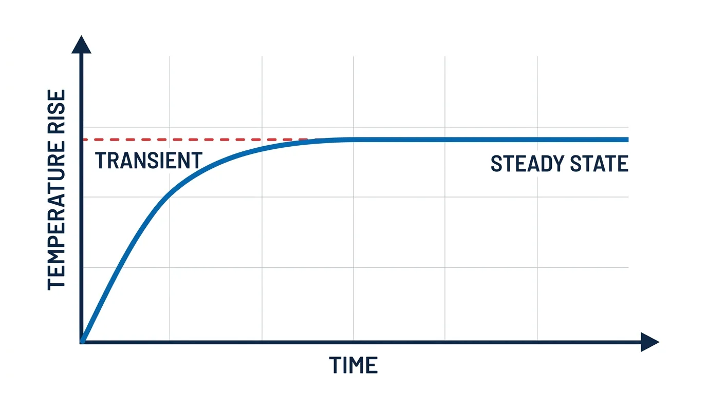
- Steady-state (thermal resistance) is what you use for continuous loads — a CPU at a sustained TDP, a power supply running flat out. If the part reaches equilibrium, Rθ tells you the junction temperature.
- Transient (thermal impedance) matters for pulsed, switching, or bursty loads — a MOSFET switching, a laser diode pulsing, an EV inverter under a short overload. Here the thermal mass buys you headroom for short events, and only Z_th(t) predicts the peak junction temperature.
Most TIM selection is a steady-state, area-normalized-impedance problem; transient Z_th mostly concerns the semiconductor and heatsink stack, not the interface material itself.
Why this matters for reliability, not just temperature
Getting the interface impedance wrong doesn’t only raise temperature — it accelerates failure. Higher junction temperatures shorten component life, and a poorly conforming TIM can also suffer pump-out or dry-out over thermal cycles, raising impedance further over time. Specifying by real impedance (and a stable material) protects both the temperature budget and the field-reliability budget.
Frequently asked questions
Is higher thermal impedance better? No — for both resistance and interface impedance, lower is better. Higher impedance means a larger temperature rise per watt across the joint.
What is a good thermal resistance value? It’s entirely application-dependent — there’s no universal “good” number. Set it from your heat load and junction-temperature budget, then choose a stack (heatsink + TIM) whose total Rθ keeps you under that budget with margin.
Is thermal impedance the same as thermal resistance? Related, not identical. Resistance is steady-state (K/W). Impedance either adds time (transient Z_th) or normalizes resistance by area for TIM datasheets (°C·in²/W). A TIM’s “impedance” already contains its resistance plus contact effects.
Should I compare TIMs by W/mK or by impedance? By impedance, at your actual thickness and pressure. W/mK ignores the thickness and contact resistance that dominate real joints.
The takeaway
Use thermal resistance (K/W) to reason about steady-state temperature across a path, and thermal impedance when time matters (transient Z_th) or when comparing interface materials (area-normalized °C·in²/W at a set thickness and pressure). For choosing a TIM, impedance is the honest number — and if you want help comparing candidate materials at your mounting conditions, ZIITEK can help compare candidate materials across its pad, paste, gel, and phase-change lines and send samples to validate against your stack.
Definitional references: Thermal conductance and resistance — Wikipedia; transient thermal impedance and RC-network modeling background from Monolithic Power Systems’ application material and JEDEC JESD51 thermal-measurement standards.