Thermal Pads for SSD & M.2: Selection Guide
Picking a thermal pad for an M.2 SSD is a gap-and-compression problem, not a W/mK contest. Measure the gap, set thickness and hardness, verify impedance.
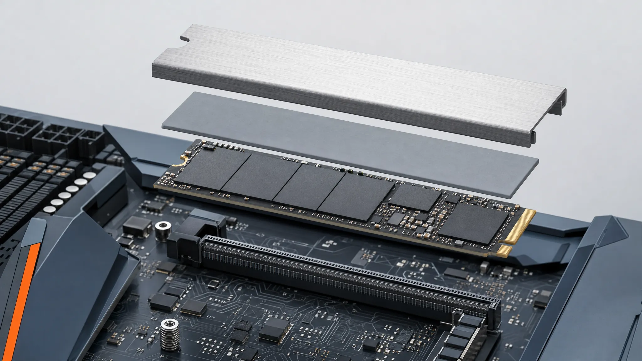
The most common way to get a thermal pad for SSD wrong is to buy it the way you would buy a phone case: pick the one with the biggest number on the box. Someone reads 16 W/mK, orders a sheet, cuts it to the M.2 outline, and then the drive either throttles anyway because the pad only touched the high spots, or the shield will not close because the pad is half a millimetre too thick.
Both failures come from the same missing step: nobody measured the gap the pad has to fill. On an M.2 slot the pad is a tolerance part, not a consumable. This guide walks the order that actually works — figure out what the pad sits on, measure the gap, choose thickness and hardness, then check the one number that predicts throttling — and shows where a fixed-thickness pad stops being the right answer at all.
Why an M.2 SSD Needs a Thermal Pad — and Where It Goes
An M.2 drive is a short PCB with a handful of large components soldered to it. The one that matters most for heat is the controller: a thin, square die in a package that sits higher than everything around it. NAND packages and the DRAM cache sit lower, and the board itself is flat. When the drive runs a sustained workload — a large file copy, a compile, a long render — the controller is where the power concentrates, and its temperature climbs fastest.
Every NVMe drive protects itself from that heat by throttling: when the controller approaches its limit, the drive slows the link and the flash to hold temperature, then speeds back up once it cools. Reporting that temperature is part of the interface itself — the NVM Express specification defines a SMART/Health log through which a drive exposes its composite temperature, which is why drive-management utilities can show it at all. On most consumer drives the ceiling sits somewhere around 70 °C — it is set per model, so confirm it against your own drive's SMART data — and sustained writes are what push a drive toward it.
A heatsink alone does not fix that. Metal sitting a fraction of a millimetre above a chip cools almost nothing, because the air in between is a poor conductor. The pad is what closes that gap: it conforms to the controller, the NAND and the shield at the same time, and gives heat a continuous path from the die into metal that has the surface area to shed it. The pad is not the cooler. It is the interface, and for M.2 the whole job is to keep the interface in contact — the same device-level thermal pad selection problem that shows up in any compact assembly.
The metal still has to pass that heat on, and a shield with no path to moving air stores it rather than shedding it; the case-level side of that chain is outside what this article sets out to solve. On a larger board the same filling-and-compression logic drives choosing a thermal pad for GPU cooling.
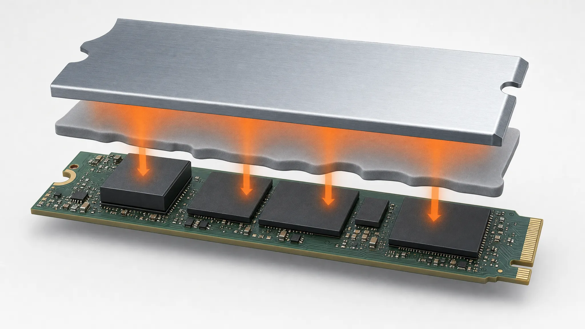
The pad has to reach the controller and the shorter packages at once: one component is taller, and the shield is flat.
The Gap Sets the Thickness: Measuring an M.2 Slot
Thickness is not chosen from a preference. It is set by the vertical distance between the top of the tallest component on the drive and the underside of the surface it has to reach — the motherboard M.2 shield, a third-party heatsink, or the tray of a two-piece cooler.
The measurement is usually easy to make and easy to skip. Assemble the drive and its shield without a pad, close the shield to its stops, then measure the standoff; or, more practically, measure the pad that came with the shield. That stock pad was cut for this exact gap: its free thickness is the spec to copy for a like-for-like replacement, but the dimension your measurement has to match is the pad's installed thickness — its free thickness reduced by the compression the shield's force produces. If there is no stock pad, feeler gauges between the shield and the tallest component give the same gap to within the tolerance you need.
Two mechanical details decide what you can actually use:
- Component height is a stack, not a single value. The controller, the NAND packages and the DRAM can differ by a few tenths of a millimetre. The pad is thick enough for the tallest one; the shorter ones rely on the pad compressing down to reach them, which is why thickness and compressibility are one decision, not two.
- Single-sided and double-sided drives are different assemblies. A single-sided M.2 has components on one face only. A double-sided drive has them on both, and a cooler designed for it may use a pad above and below the PCB. Do not add a bottom pad to a single-sided drive just because there is space — an unnecessary pad underneath changes how the top shield seats and can load the board. Follow the cooling hardware's own arrangement.
It also helps to know what you are specifying against. The M.2 form factor allows module widths of 12, 16, 22 and 30 mm, and 22 mm is the width the common SSD modules use; within that family the modules are named by length — 2230, 2242, 2260, 2280 and 22110 — where 2280 (22 × 80 mm) is the common desktop size and 2230 shows up in handhelds and thin laptops. Those dimensions come from the M.2 form-factor specification published by PCI-SIG, and while the module size fixes the outline of the pad, it says nothing about its thickness — that still comes from the gap.
Get the thickness wrong and the failure is predictable. A pad thinner than the gap leaves part of the interface as air and the drive still runs hot. A pad thicker than the gap stops the shield closing flat, bows the PCB, or loads the solder joints under the controller. The method for turning a measured gap into a specified thickness — including how a soft pad is gauged under load — is set out in thermal pad thickness and compression.
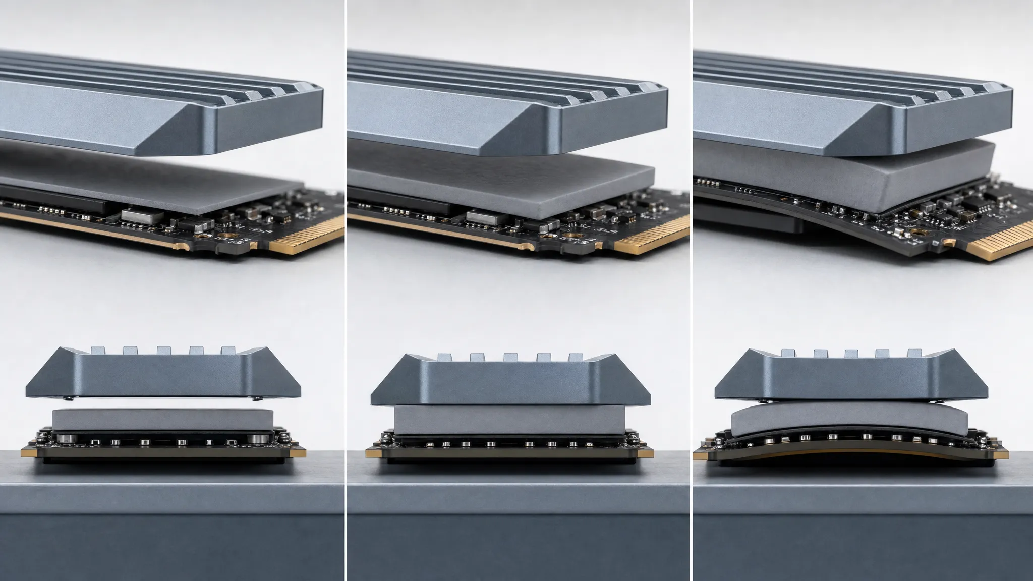
Thickness is a tolerance, not a preference: under-sized leaves air, over-sized bows the board.
Hardness and Compression: Matching the Pad to the Assembly
A pad is specified at its free thickness, but it never works at its free thickness. Closing the shield compresses it, and the installed thickness is what bridges the gap. That is why the hardness number matters as much as the thickness number.
Hardness on soft pads is quoted in Shore OO. The range runs from very soft compounds that conform under almost no force to firmer ones that hold their shape under a heavier shield. For an M.2 slot the shield usually applies modest force through its own screws or clips, so a soft grade does most of the work: it deflects into the recesses between the controller and the shorter packages and reaches surfaces a stiffer pad would sit above. A firmer pad is the choice when the assembly applies real clamping force and you want the pad to sit in the gap rather than squeeze out of it.
The practical question is not "how hard is it" but "at the force this shield applies, does the pad compress enough to touch everything, without compressing so far that it stops pushing back." The scale for that judgement is not a single percentage: it is the grade's compression-deflection curve, read at the load the shield applies. Two conditions fall out of it. At the tallest component the pad has to deflect down to the gap. At the shortest component it has to still be under compression, so its installed thickness there stays positive — a grade that is too firm fails that second test, and one that is too soft can take a set and stop pushing back. Because both conditions read off the same curve, thickness and hardness are chosen together, and the grade is picked against the assembly rather than by the size of its number.
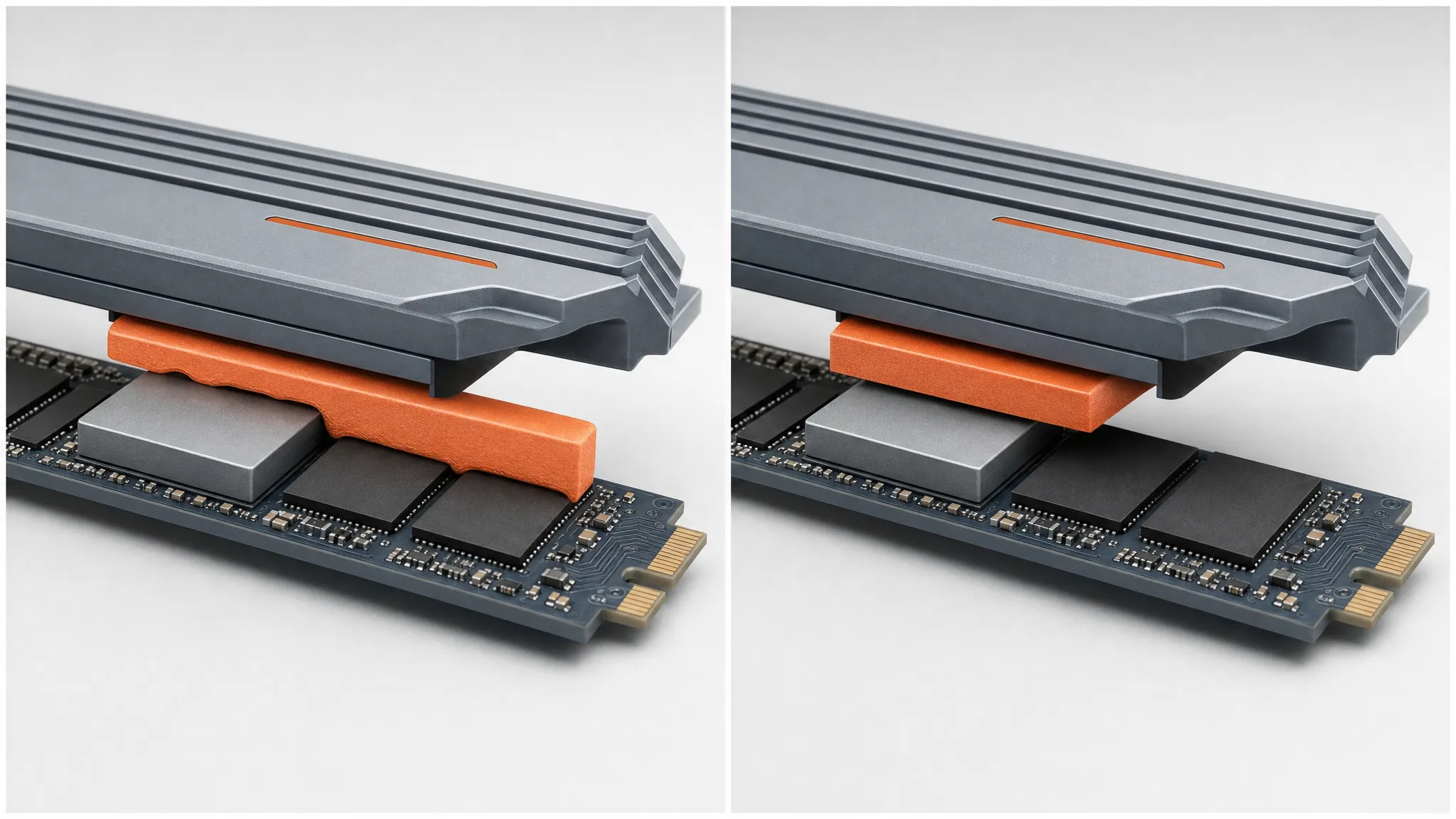
A soft grade closes the gap to every component; a firmer one can bridge the tall chip alone and leave the short packages in air.
This is the point where pad selection and thermal performance meet: compression sets how much of the pad is actually in contact, and contact is what the thermal number depends on. Which brings up the number most buyers start with — and the reason it can lead them the wrong way.
Why W/mK Alone Misleads — the Number That Predicts Throttling
W/mK, the material's bulk thermal conductivity, is the figure on every datasheet and the one that gets compared first. It is a real property, but for a thin pad in a small gap it is not the figure that predicts whether the controller throttles, because the conductivity of the material is only one of the resistances in the path. The others — the contact resistance at the pad's two faces and the conductance through the pad's thickness at the pressure the assembly actually applies — can dominate a thin interface.
The comparable number is thermal impedance measured at a defined pressure and bond-line thickness. ASTM D5470, the standard test method for the thermal transmission properties of thermally conductive electrical insulation materials, measures steady-state thermal impedance under flat-plate conditions and derives apparent conductivity from a series of thicknesses. The catch is worth stating: those flat-plate values are the right basis for comparing one grade with another, but they are not transferable to an assembly where the surfaces are not flat, parallel and uniformly loaded. Your M.2 slot is one of those assemblies, so the number you want is impedance at your pressure and your installed thickness — not the headline W/mK.
Two consequences follow. First, a higher-W/mK pad compressed to the wrong thickness can easily perform worse than a lower-W/mK pad compressed correctly. Second, comparing two pads by W/mK alone compares the smallest part of the answer. Where the material does matter is in the range it offers and the compliance that comes with it:
| Material | Thermal conductivity | Thickness | Notes for a tight slot |
|---|---|---|---|
| TIF® thermally conductive silicone pad | 1.25–16 W/mK | 0.25–12 mm | Soft grades from 5 to 70 Shore OO; UL 94 V-0; the general M.2 choice |
| TIR®700 carbon fiber thermal pad | 9–25 W/mK | from 0.30 mm | Ultra-thin, low pressure; for very tight height budgets |
| Z-Paster®100 non-silicone thermal pad | 1.5–10 W/mK | 0.25–5.0 mm | No silicone; where outgassing near optics or contacts is a concern |
| TIF® one-component thermal gel | 1.5–9.0 W/mK | dispensed, 0.1–0.4 mm BLT | Flows into an uneven profile; see the section below on when a pad is wrong |
The figures above are series-level datasheet ranges for bulk thermal conductivity. They characterise a class of material and have to be read together with the test method and the thickness conditions behind them — they are not a standalone basis for ranking one grade against another, and they are not a prediction of installed performance. The comparable number for a given assembly is the impedance at that assembly's pressure and installed thickness, which is a separate figure to request or to read off the grade's own curve rather than from these ranges.
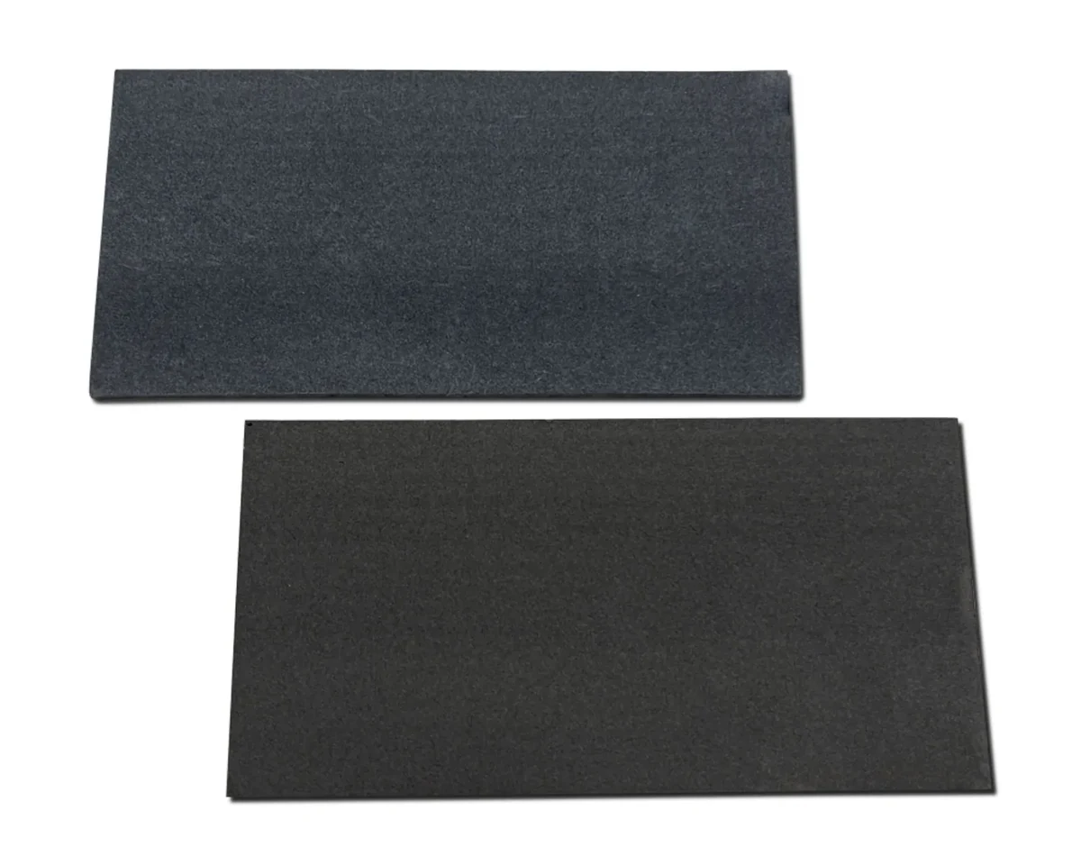
Carbon-fiber grades trade silicone compliance for a very thin, low-pressure interface — useful when the height budget is the binding constraint.
If you want the distinction between the two thermal numbers worked through, thermal resistance versus thermal impedance draws the line between the datasheet figure and the number the assembly produces.
When a Thermal Pad for SSD Is the Wrong Answer for an M.2 Slot
A die-cut pad is the default for a reason, but it is a fixed-thickness, flat part, and some M.2 assemblies do not fit that description. Four situations point elsewhere:
- The gap is very small. Below roughly a quarter of a millimetre, a pad has little to compress and its two contact resistances dominate; a thermal paste or a dispensable putty fills a thin gap with less interface resistance. The trade-off is that a paste can pump out over thermal cycles, so for a production part the putty or gel route is usually safer than a grease.
- The components are uneven. If the board mixes a tall controller with noticeably shorter parts, a single flat pad has to compress a long way at the low points to reach them. A dispensed gap filler conforms to the whole profile at once, so it can be the better fit — this is choosing a thermal gap filler territory rather than a pad decision.
- The assembly is automated and high-volume. A one- or two-component gel dispensed on the line removes the peel-and-place step a die-cut pad adds, and handles several component heights in one shot. A one-component thermal gel covers 1.5 to 9.0 W/mK at bond lines from 0.1 to 0.4 mm.
- The constraint is spreading, not conduction. In a very thin device where the problem is moving heat sideways to a larger plate rather than across one gap, an anisotropic graphite sheet does that job better than a pad — see graphite heat spreaders for thin devices.
There is a corollary on the other side. More thermal material is not automatically better. A pad stacked on top of a drive that already has an integrated heatsink, or a second pad added under a single-sided drive because the space is there, both change the mechanics for no gain. The rule is the same in every case: match the pad to the gap and the mounting, rather than adding material to a slot that already has it.
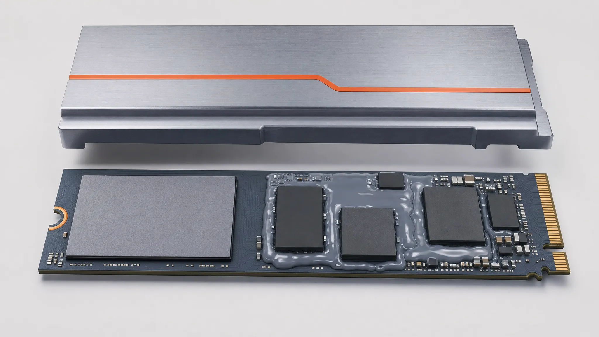
One flat pad suits a single dominant component; a dispensed gel suits an uneven profile across several.
An M.2 Thermal Pad Spec Checklist
Before you send a pad to be cut — or order one — pin these down. Every item exists because leaving it out is how the part ends up back in review.
| # | Item | What to record |
|---|---|---|
| 1 | Components and heights | Which package is tallest (usually the controller), and the height of the lowest one the pad must also reach |
| 2 | The gap | Free gap between the tallest component and the shield, measured with the drive seated |
| 3 | Drive and cooler type | Single-sided or double-sided SSD; motherboard shield, aftermarket heatsink, or two-piece tray |
| 4 | Assembly force | The load the shield applies when closed, and the compression that produces |
| 5 | Target thermal value | Impedance at that pressure and installed thickness, not just W/mK |
| 6 | Compliance | Flame rating (UL 94 V-0 where required), silicone or non-silicone, and any automotive or export documentation |
| 7 | Supply format | Die-cut to the M.2 outline, sheeted, or a dispensable gel, matched to how the line builds the drive |
Item 3 is the one most often left out, and it changes every number after it: a double-sided drive with a two-piece cooler is a different specification from a single-sided drive under a motherboard shield.
If you would rather hand the constraints to someone who compresses these grades every day, ZIITEK's engineers will recommend a pad or gel grade for your gap, force and compliance requirements and send samples to test. Start from the thermal pad product range.