Liquid Metal TIM for Data Centers: When to Use
Decide whether liquid metal TIM belongs in a data center build: five signs it earns its place, five constraints that rule it out, and a supplier checklist.

Start With the Interface, Not the Material
A 700 W accelerator and a 1 kW module built for liquid cooling put the same question back on the table every design cycle: what holds the heat path together where the silicon meets the cold plate? Liquid metal TIM for data center hardware is the answer some teams reach for first, because the numbers look unbeatable: a gallium-based liquid metal thermal interface material conducts heat at 25 W/m·K or more, and it stays liquid instead of drying out. Others rule it out on sight, because a metal that flows is also a metal that shorts, migrates, and reacts with the wrong surface.
Both instincts are half right, and neither is a decision. The decision is a qualification problem, and this guide works through it the way an engineer would: what the interface actually demands, when a liquid metal earns its place, what rules it out, and what to demand from a supplier before you commit a board.
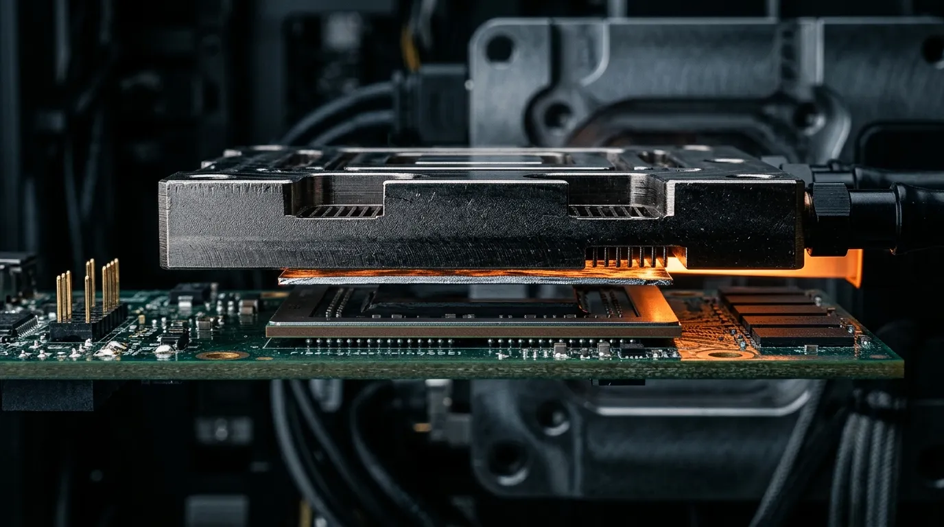
The first thing to fix in your head is which interface you are talking about. Modern accelerator modules are not a die bolted to a heat sink. They are a stack: TIM1 between the die and its lid or heat spreader, TIM1.5 between a bare die and the cold plate in lidless, top-side-cooled designs, and TIM2 between the lid and the cold plate. Each layer sees a different heat flux, a different clamp load, and a different tolerance for thickness variation. Some suppliers number these interfaces TIM0 and TIM1 instead, so confirm which layer a data sheet number refers to before you compare two of them.
That last part is what breaks naive material comparisons. Large accelerator packages are not flat, and they do not stay flat. Measured warpage on big body sizes is commonly reported in the ±50 to ±150 µm range at room temperature, and peak-to-valley deformation often grows to 100–300 µm after reflow or under thermal load; past 50 mm body sizes, corner deflection in the hundreds of micrometers has been reported, with extreme cases beyond 300 µm. When the target bond line is 20–100 µm, the warpage can equal or exceed the thickness of the layer trying to bridge it (IEEE EPS newsletter on TIM strategy for AI and HPC, 2026).
Read that as a rule about interfaces, not materials: once the gap is not uniform, a lower-conductivity material that keeps intimate contact everywhere can beat a higher-conductivity material that voids in the low-pressure regions or gets pushed out of the high-shear ones. That is the lens this whole article uses. If you want the wider material map first, start from our hub on thermal materials for data centers and AI servers, or the step-by-step comparison in our selection guide for thermal interface materials on AI hardware.
If you only read one table in this article, read this one. Everything below it is the reasoning.
| Your interface looks like this | Liquid metal TIM verdict |
|---|---|
| Bare die against a nickel-plated copper cold plate in a 700 W+ module | Strong candidate — shortest path, highest payoff |
| Large, warped package where you cannot raise clamp load further | Candidate — a fluid layer conforms where a solid one voids |
| Immersion or direct-to-chip loop that excludes organic TIMs | Candidate — but only with containment signed off |
| Unplated aluminum anywhere in the wetted path | Rule out — the alloy reacts with aluminum |
| Field-reworkable module, or a low-power part with thermal headroom | Rule out — the rework and cost penalty buys nothing |
When Liquid Metal TIM Earns Its Place
There are five conditions that, in combination, make a liquid metal the right answer rather than an expensive experiment.
1. The interface is close to the silicon, and the heat flux is extreme. A lidless TIM1.5 joint (bare die to cold plate, no heat spreader in between) has the shortest thermal path and the tightest margin. It is also the interface where a thin, highly conductive, fully wetting layer changes the junction temperature most. This is where liquid metal pays off first.
2. Your thermal budget is set by the interface, not by the cooling loop. Liquid metals have intrinsic conductivity typically above 25 W/m·K and are commonly reported with total interface resistance below 0.05 K·cm²/W when wetting and containment are controlled. For comparison, the same IEEE analysis puts thin solder TIMs at 0.02–0.08 K·cm²/W and compressible metallic TIMs at 0.05–0.15 K·cm²/W depending on pressure and geometry. If a fraction of that difference moves your junction temperature out of a throttling band at fixed fan or pump power, the premium is easy to justify.
3. The package is large and warped enough that clamping harder is not an option. A liquid layer conforms to non-planarity instead of fighting it. Increasing clamp load can reduce measured warpage and improve contact in a test fixture, but it also raises shear stress on the die and package, a trade you stop having to make when the interface material itself is fluid.
4. The cooling architecture is metal-only by requirement. Immersion and direct-to-chip deployments put materials in contact with coolant chemistry. Organic chemistries such as greases, gels, and some phase change materials can swell, leach additives, or change viscosity in dielectric fluids, which compromises the bond line over time; fully metallic systems do not depend on an organic matrix for compliance. Liquid metal fits that constraint, provided it is contained (see the next section, which is where most liquid metal programs actually fail).
5. The failure mode you are trying to design out is pump-out, not cost. Highly compliant, grease-like materials are the most exposed to shear-driven migration under power cycling. A material with no organic phase to dry out or separate addresses that specific failure mode. If your field failures are thermal drift rather than cold-start performance, this is the case to make.
The technology is no longer experimental, which matters when you have to defend the choice in a design review. Liquid metal has been in volume production: Sony's PlayStation 5 put it in a consumer console, and NVIDIA moved its flagship RTX 5090 graphics card from thermal paste to liquid metal to manage a 575 W TGP (Tom's Hardware, 2025). Market forecasts point the same way: TIM revenue is projected to grow at more than 10% CAGR between 2026 and 2036, with data centers and advanced packaging among the faster-growing applications (IDTechEx). What those deployments prove is manufacturability, not that the material suits a low-flux interface — the console and consumer-GPU examples sit at the power levels where the argument for liquid metal is easiest.
The Constraints That Can Rule It Out
Now the other half, which is where the honest answers live. Any one of these five can end the discussion.
Bare aluminum anywhere in the wetted path. This is the hard stop. Gallium-based alloys are corrosive toward most metals, and aluminum in particular is off limits: supplier data sheets state that these materials must not be put in contact with most metals including aluminum, and that copper heat sinks and integrated heat spreaders should carry at least a 20 nm electroless nickel plating (Indium Corporation liquid metal TIM data sheet). If your cold plate or heat sink is unplated aluminum, liquid metal is not a candidate; if you cannot control the plating on incoming parts, it is not a candidate either. Coatings look like an escape route, and the supplier guidance on this point is blunt: applying a gallium-based alloy to aluminum or its alloys, or trying to protect the aluminum by anodizing it, is not an acceptable use (Indium Corporation liquid metal FAQ). If your platform is locked to aluminum, the answer is a different interface material (a compressible metal, a gap filler, or a pad) or a different wetted surface.
Any path to a short circuit. The material is a metal — gallium alloys sit on the order of 10⁻⁷ Ω·m — and it will be sitting millimeters from power rails and high-speed traces. Supplier guidance is explicit on both halves of this: liquid metals are electrically conductive and should not come into direct contact with circuitry, and metallic TIMs are the wrong choice where electrical isolation is required unless an isolation layer goes in with them. A defined containment geometry, a perimeter barrier, and a limit on how much alloy is dispensed are part of the design, not application details to be settled on the line.
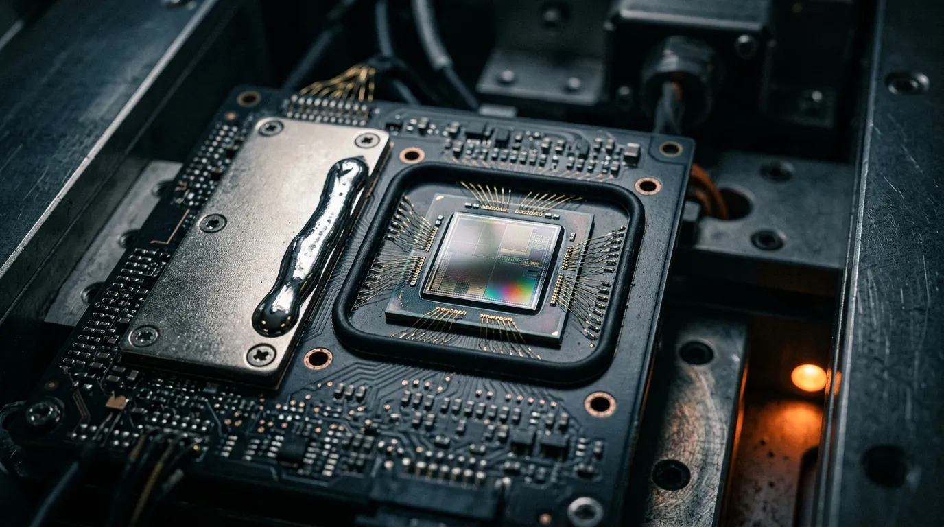
Migration and containment under cycling. A fluid interface has to stay where you put it. Power cycling, thermal expansion mismatch, and vibration all load the layer in shear. Fluid behavior also means the bond line is set by the mechanical design (a dam, a shim, or the clamp geometry) rather than by the material's own thickness, so containment is what stabilizes BLT.
Serviceability. Reworking a liquid metal joint is not a paste swap. Removal, cleaning, surface preparation, and re-dispensing all need a documented procedure, and the die-side surfaces have to be re-qualified after opening. If your service model assumes field replacement of modules, price that procedure into the decision now rather than after the first RMA.
Cost, handling, and supply. Liquid metal is a specialty alloy with a shelf-life and storage discipline attached. For a low-power part in a benign thermal environment, none of its advantages are reachable and the cost is pure overhead. Save it for the interfaces where the thermal margin is actually scarce.
Treat liquid metal as a containment and metallurgy decision first, and a thermal-conductivity decision second. The conductivity figure is what makes you look; the metallurgy and the containment are what decide whether it ships.
Read the Numbers in the Right Units
Most bad liquid metal decisions start as unit errors, so slow down here. Thermal conductivity (W/m·K) describes the bulk material. Total interface resistance (K·cm²/W, sometimes quoted as °C·in²/W) describes the assembled joint: thickness, contact on both faces, and pressure included. They are not convertible, and a supplier that quotes only W/m·K has not told you what your stack will do.
Compare materials in W/m·K. Compare assembled interfaces in K·cm²/W. Mixing the two is where most of these decisions go wrong.
The joint resistance decomposes into a bond-line term and two contact terms, and in thin, well-filled joints the contact terms can dominate. That is why thermal resistance and thermal impedance are the numbers to compare across material families, and why what W/m·K actually measures is a within-family metric.
It is also worth knowing what a standard measurement does and does not cover. ASTM D5470 measures thermal impedance in steady state, driving heat through a specimen clamped at a known pressure and thickness (ASTM D5470). It was written for electrically insulating specimens, so metal-based TIMs are tested either with an insulating pair in the stack or as a full stack, which is worth remembering before you line a liquid metal number up against a pad number. That geometry is idealized next to a warped package with partial contact, which is the same reason the IEEE analysis cited above argues that steady-state resistance measured under uniform pressure is no longer enough to predict field performance: qualification has to add shear, thermal cycling, and warpage-aware testing. So when a data sheet number arrives, ask what pressure, what bond line, what surface finish, and whether it was remeasured after aging.
A Qualification Checklist You Can Hand to a Supplier
This is the part to copy into a supplier questionnaire. Each item is something a competent TIM supplier can answer with data, not adjectives.
- Wetted materials. List every surface the alloy touches (die side, plate side, any intermediate layer), with the plating specification for each (for copper, an electroless nickel layer of 20 nm or more is the common recommendation). Ask for a written compatibility statement per material.
- Total interface resistance at your conditions. Request K·cm²/W at your clamp pressure, your bond-line target, and your operating temperature band, not a single bulk conductivity figure.
- Bond-line control method. How is BLT set and verified: a dam, a shim, a dispense volume, or clamp stiffness? What ΔBLT does the process tolerate across the package?
- Containment and migration data. How does the alloy behave under power cycling and lateral shear, and what test did the supplier run to show it stays in place?
- Cycling durability with resistance monitoring. Thermal or power cycling with interface resistance drift tracked over cycles is the number that predicts field behavior; a pristine day-one value does not.
- Dispensing and packaging for your volume. Syringe, cartridge, or automated dispense, plus shelf life, storage orientation, and pot life if the alloy is supplied as a paste.
- Compliance documentation. RoHS and REACH declarations and a safety data sheet for the specific alloy, issued for the finished article you are buying.
- Rework procedure. A documented removal and re-application process, including what happens to the die-side surface after opening.
Two of these eight items, wetted materials and cycling durability, are the ones that most often re-open a qualification late. Get them in writing before tooling.
Where a Liquid Metal Thermal Interface Material Sits in the Mix
Liquid metal is not the default; it is one point on a spectrum that runs from thick and forgiving to thin and unforgiving.
| Material | Where it fits | Rework | Main risk |
|---|---|---|---|
| Silicone thermal pad | Thick gaps, low pressure, high-volume assembly | Easy | Contact resistance at high heat flux |
| Dispensed gap filler / gel | Irregular thin gaps, automated lines | Moderate | Pump-out in high-shear interfaces |
| Phase change material | Moderate flux where you want pump-out resistance without a fluid metal | Moderate | Activation temperature and clamping needed; not a metal |
| Silicone grease or paste, filled or unfilled | Lowest-cost interfaces and field service | Easy | Pump-out and dry-out; filled versions are limited by the filler network, not the polymer |
| Gallium-based liquid metal | Extreme heat flux, compatible metallurgy, qualified containment | Hard | Aluminum contact, short-circuit path, migration |
| Liquid metal paste or composite | High-volume dispensing, where placing a pure alloy is impractical | Moderate | Same containment and wetted-material rules; lower bulk conductivity than a pure alloy |
| Graphite sheet | Thick gaps and low pressure where a metal-free path is preferred | Easy | Peak conductivity is lower, and thickness drives the resistance |
The boundary rules are short. If your gap is thick and your pressure is low, a pad or a thermal gap filler is the practical answer. If you need pump-out resistance at moderate flux without a metal, phase change materials do that job with a fraction of the containment burden. Liquid metal becomes the answer only when the interface resistance itself is the constraint and the mechanical and materials conditions above are satisfied. Two families sit at the edges of this table: liquid metal pastes, formulated with a higher viscosity so they can be dispensed predictably at production volume (Indium Corporation high-performance TIM handout), and graphite sheets, which trade peak conductivity for thickness tolerance and a metal-free interface.
Specifying a Liquid Metal TIM
If you have decided to qualify, write the spec so it cannot be satisfied by a datasheet headline. A usable liquid metal specification names the alloy family (gallium-based), the interface it is qualified for (TIM1.5 or TIM2), the total interface resistance at stated pressure and bond line, the operating temperature range, the electrical resistivity, the required plating on wetted surfaces, the containment geometry, and the dispensing format.
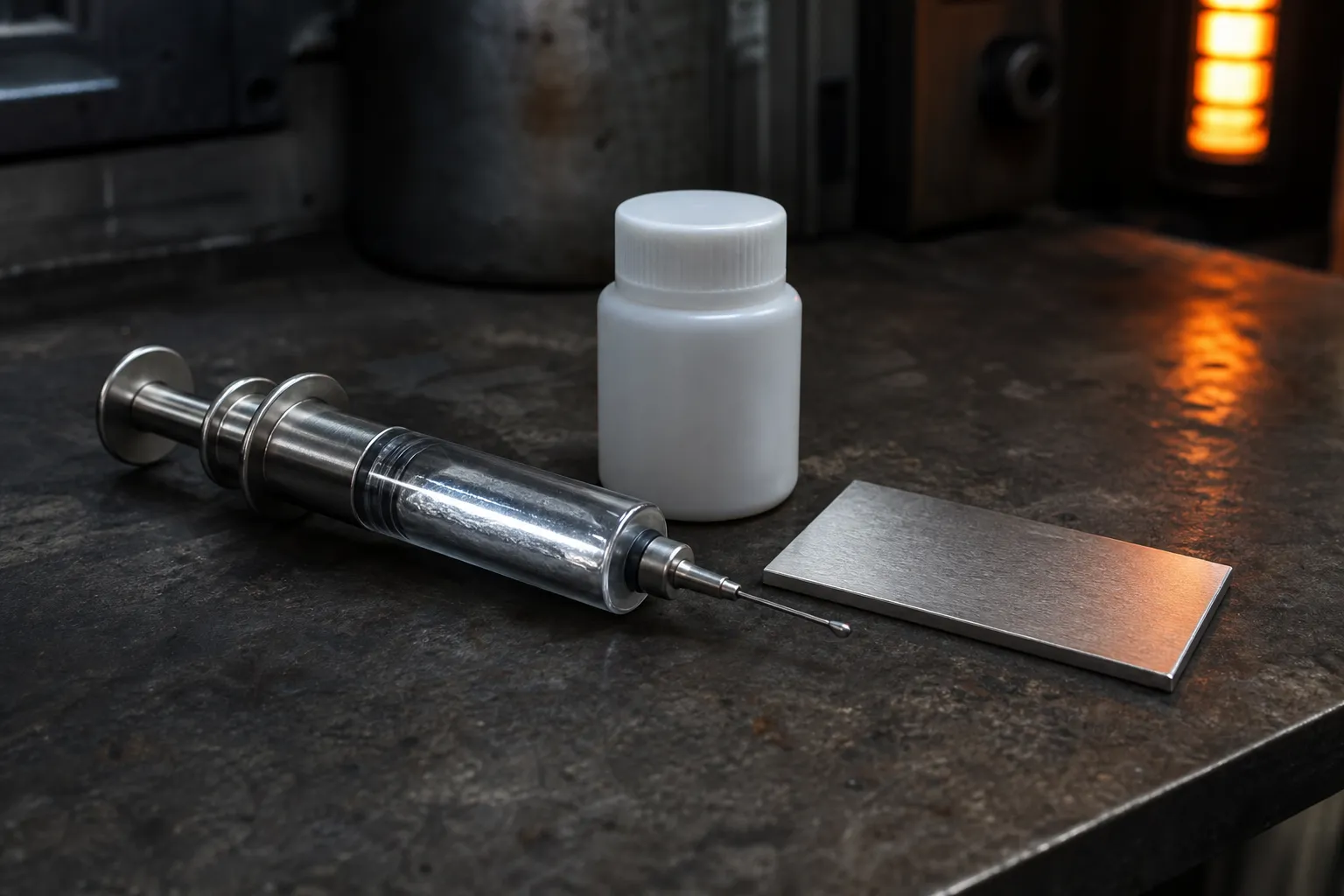
ZIITEK's Liquid Metal series is rated at 35 W/m·K and supplied as a silver-colored alloy that is solid at room temperature and molten in service, with a melting point above 60 °C, a resistivity below 10⁻⁷ Ω·m and a working range of –40 to 250 °C. The series data describes it as non-volatile and non-toxic, and it is used on CPUs, GPUs, chipsets, set-top boxes, and LED assemblies. Those are properties of the material itself, and they do not change the rule from the constraints section: the metals your assembly exposes to the alloy still have to be reviewed against it, because gallium-based alloys interact with aluminum regardless of who supplies them.
What a supplier relationship adds at that point is the boring part that decides whether a qualification survives production: a plating specification you can audit, a containment geometry reviewed against your cold plate, and one quality system behind the pad, gap filler, grease, phase change, and liquid metal options so you are not integrating four vendors on one board. That system is also what carries the paperwork an engineer has to put into a design review: IATF 16949, ISO 9001, ISO 14001 and QC 080000 certification, RoHS and REACH documentation behind the product families, and one process standard across four manufacturing bases. If your interface is a nickel-plated copper cold plate over a bare die and a pad or gel cannot reach the resistance you need, send us the stack and we will review the interface with you.
Short Answers to the Questions Engineers Ask Most
Can I just take the highest W/m·K material available? No. Bulk conductivity is a within-family metric; the assembled joint (bond line, contact on both faces, pressure) decides the temperature. In a warped interface, a material that maintains contact can outperform one that conducts better on paper and voids in service.
Does liquid metal need re-application over the product life? It has no organic phase to dry out or separate, so it does not fail the way a grease does, but the aging risk moves rather than disappears. Gallium diffuses into unplated copper, which the supplier data sheet quoted above links to early failure in parts that see variable temperatures, and the alloy's own surface oxide is part of how it wets. Both faces of the joint therefore stay part of the reliability story, which is why checklist items 1 and 5 carry the weight and why a documented procedure is still needed if the module gets opened.
What are the real handling risks? Two engineering risks, not one. The alloy is electrically conductive, so containment and dispense volume are the safety margin against shorts; and it must not contact aluminum, so the wetted-materials list is the other. ZIITEK's series data describes its liquid metal as non-toxic; ask for the safety data sheet for the exact alloy you are buying and follow it for storage and handling. Note also that these alloys wet non-metallic surfaces as readily as metal ones, so storage and dispensing hardware is part of the specification too — supplier data, for instance, calls for syringes to be stored tip down.