Thermal Runaway: Materials That Help Contain It
How mica, aerogel, ceramic-fiber and silicone-foam barriers slow thermal runaway propagation between cells, and the specs to check before you specify.
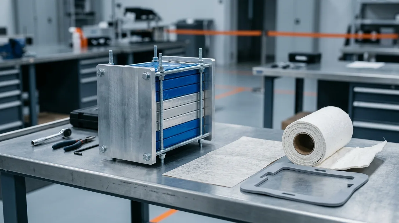
Thermal Runaway Is a Propagation Problem Before It Is a Cell Problem
A single lithium-ion cell going into thermal runaway is a bad day. A pack that carries that failure from cell to cell is a recall, a fire, and a redesign. The two events are separated by a thermal barrier — or by the absence of one.
Thermal runaway itself is a self-accelerating chain of exothermic reactions: an internal short, an overcharge, a manufacturing defect or external heat damages the separator and the solid electrolyte interphase. The anode-electrolyte reaction initiates in the 70–90 °C band depending on chemistry and design; held in an adiabatic environment at that temperature, a cell will self-heat to runaway within days. Polyethylene or polypropylene separators shut down their pores at 130–150 °C before they melt (NRC, Lithium-Ion Batteries Hazard and Use Assessment). Once the sequence is under way, case temperatures on fully charged cells can exceed 600 °C, and internal temperatures reach the 660 °C at which the aluminium current collector melts. Nothing a materials engineer specifies will stop that cell. What materials decide is whether the next cell, and the cells behind it, join in.
That distinction is the whole design brief. This article covers containment: the material classes that sit between cells and around modules, the properties that make a barrier work, and the numbers worth demanding from a supplier before you approve a sample. For the wider system view — cells, cooling plates, sealing, heating — start with the EV battery thermal management materials guide, which maps the topic.
Where the Heat Actually Goes: Three Paths Between Cells
Most "battery fire barrier" discussions treat propagation as a conduction problem. It is not, or at least not mainly. In the air experiments on a dense 18650 array with no gaps and no barriers, roughly 50% of the heat flow to downstream cells came from flaming combustion of ejected material, about 20% from direct cell-to-cell conduction, and the remainder from convection and radiation (IOP). Different cell formats shift those proportions — a prismatic cell with a wide face contact conducts more than a cylindrical one — but the ordering is a useful corrective.
The three paths, and what each one asks of a material:
- Conduction through contact. Cell face to cell face, cell base to cold plate, module wall to module wall. Interrupted by low-conductivity solids and by air gaps. This is the path a barrier material addresses most directly.
- Ejecta and flaming combustion. A venting cell throws hot particles, solvent vapor and flame out of its vent. That jet does not care about the thermal conductivity of a sheet in its way; it cares whether the sheet survives the impingement, whether it blocks the vapor from condensing on the neighbouring can, and whether the gas has somewhere else to go.
- Radiation and hot gas convection. The slowest path, but the one that matters after the first two have been blunted, because it keeps loading the adjacent cell for tens of seconds.
The design consequence: a barrier plus a vent path, not a barrier alone. A module that traps ejecta behind an intact sheet turns a propagation problem into a pressure problem.
| Path | Share of heat flow (in air, dense 18650 array, no barriers) | What interrupts it | Material implication |
|---|---|---|---|
| Ejecta and flaming combustion | ~50% | Blocking vapor deposition on the neighbouring can, plus a vent route away from cells | Flame-stable barrier + vent channel; insulation alone is not enough |
| Direct contact conduction | ~20% | A low-diffusivity solid of adequate thickness | Mica, ceramic fiber, aerogel at the cell-to-cell interface |
| Convection and radiation | remainder | Thickness, low emissivity, residence time | Same barrier, but performance is thickness-driven |
Thermal runaway containment is a routing problem before it is a materials problem.
What a Containment Material Has to Do
A battery thermal barrier is asked to satisfy four requirements at once, and they pull against each other.
Low thermal diffusivity, not just low conductivity. A barrier sees a step input, not a steady state. What matters is how fast the far face heats: thermal diffusivity (conductivity divided by density times specific heat) combined with thickness. This is why thin, low-density materials can outperform thicker, denser ones — and why a 1 mm aerogel blanket and a 1 mm mica sheet behave nothing alike.
Structural survival under flame. The sheet has to stay a sheet while a 1,000 °C jet is aimed at it. Phlogopite mica and ceramic fiber hold their form; thermoplastic films sag, melt and drip. A barrier that fails mechanically at 300 °C has no thermal performance left to discuss.
Dielectric strength. The barrier sits between cells that are electrically live relative to each other and to the enclosure. Insulation is not a bonus feature; a conductive barrier is a short circuit waiting for a fault.
Compressibility and mass. Cells swell, stack tolerances stack up, and the pack has to be built on an assembly line. Foam-based barriers absorb tolerance and vibration while insulating. Rigid mica contributes nothing to tolerance and must be paired with a compliant layer. Every gram of barrier is a gram of lost energy density, which is why the industry keeps pushing toward thinner, lighter systems.
One clarification worth stating plainly, because it causes real design errors: a thermal interface material is the opposite of a barrier. Gap fillers and pads are specified to minimize interfacial resistance between a cell and a cold plate. Put the same material between two cells and you have built a heat bridge. The gap filler selection guide for EV battery modules covers the conduction side; if you need the zone-by-zone map of a pack, the EV battery pack thermal management guide lays out all five thermal zones.
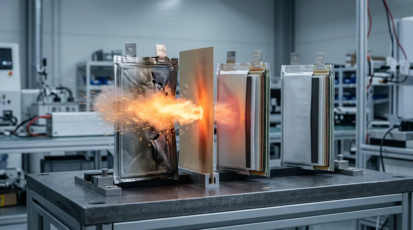
Illustration: a venting cell's ejecta jet striking an inter-cell barrier sheet that does not cover the full cell face — the jet finds the exposed edge and carries on to the next cell. That is the failure the placement section below warns about, and the reason barrier selection has to account for the jet, not only for conduction through metal.
The Material Classes That Do the Work
Five thermal barrier classes cover almost every containment design, and the differences between them are mechanical as much as thermal.
Mica and mica-composite barriers
Mica is the incumbent fire barrier in EV packs for unglamorous reasons: it is cheap, it is dielectric, it does not burn, and it is available in grades that hold their structure at cell-fire temperatures. The grade matters more than the material name, and this is where designs go wrong. Phlogopite mica is the high-temperature grade: roughly 700 °C continuous service, with intermittent exposure to about 1,000 °C; muscovite — cheaper, more common, easier to source — is a 500–600 °C continuous material that loses structural water above roughly 600 °C. "Mica is a 1,000 °C material" takes an intermittent rating and bills it as a continuous one, and it is roughly double the real continuous rating of the muscovite grade. In practice it appears as mica paper laminated to glass cloth, PET film or a thin foil for handling strength, die-cut to the cell footprint or to a module-lid profile.
Where mica wins: cell-to-cell partitions in prismatic and pouch modules, module lids, and the firewall between the pack and the passenger compartment. Where it loses: it is rigid and brittle, it offers no compression, and it does not absorb mechanical tolerance. It is usually paired with a foam or a compressible pad on one face.
Ceramic fiber and intumescent barriers
Ceramic fiber board and paper occupy the same temperature class as mica with better conformability and lower density. They were also the most effective barrier in the passive-mitigation study cited above: a 3.2 mm ceramic fiber board on a stainless steel backing plate cut thermal runaway propagation speed by more than a factor of 30 across 12–15-cell arrays. The steel is part of that number — the authors report that both the ceramic fiber and the intumescent material broke in testing when used unsupported. Across physical barriers as a class, the paper's own conclusion is a reduction of more than a factor of 17, and no tested strategy prevented propagation outright (IOP). Intumescent systems take a different route: they expand and char when heated, forming a thick insulating layer exactly where the flame is, which makes them attractive for vent paths and enclosure penetrations where the geometry is awkward for a rigid sheet.
Two cautions with ceramic fiber. First, dust and fiber release during die-cutting is a handling issue that needs a converting process built for it. Second, "ceramic" describes a family, not a specification — fiber chemistry, binder burnout temperature and density vary enough that two boards of the same thickness can differ by a factor of two in through-thickness performance.
Silica aerogel blankets
An aerogel thermal barrier is the thinnest credible option: silica aerogel held in a fiber batting, with thermal conductivity around 0.015–0.02 W/m·K at ambient, and the best performance per millimetre of anything in this list. For a pack chasing energy density, 1–3 mm of aerogel replacing 3–5 mm of ceramic board is a real gain.
The costs are mechanical and commercial. Aerogel blankets are dusty, friable, and sensitive to compression and shear during assembly — they need encapsulation or a carrier film, and the die-cutting has to be clean. Price per square metre is the highest of the classes here, which is why aerogel usually appears as a targeted inter-cell barrier rather than a full-pack liner.
Silicone foam: insulation, compression and sealing in one part
Silicone foam is the class that solves the tolerance problem. At around 0.06 W/m·K it insulates an order of magnitude better than a thermal pad, and unlike mica or ceramic it compresses: a foam gasket absorbs cell swell, stack tolerance and vibration while holding a seal. ZIITEK's Z-FOAM®800 series, for example, is rated UL 94 V-0 and IP68, with compression set at or below 5% and a service range of −40 to +200 °C — which is what lets one part act as cell spacer, cushion and enclosure seal.
What silicone foam does not do is survive direct flame impingement indefinitely, and it is not a substitute for a mica or ceramic sheet at the cell-to-cell interface in a high-energy module. Its place is the module frame, the enclosure groove, the compression pad behind a rigid barrier, and the cell spacer where the requirement is insulation plus compliance rather than a fire wall. The sealing side of the same family is covered in the silicone foam gasket guide.
Endothermic and phase change buffers
A phase change material or an endothermic barrier absorbs heat at a near-constant temperature while it melts or decomposes, which buys time without adding a conductive path. Composite designs pair a ceramic or mica skeleton — which holds the geometry and blocks the particle jet — with a phase change or intumescent filler that absorbs the transient in the seconds before the filler is spent. The skeleton does the structural work; the filler does the thermal work.
The honest limitation is capacity. A buffer with finite latent heat delays propagation by seconds to tens of seconds, then it is spent. It is a delay mechanism that helps a pack pass a test window; it is not a firewall.
| Thermal barrier class | Typical thickness | Thermal character | Mechanical behaviour | Best position in the pack |
|---|---|---|---|---|
| Mica composite | 0.3–2 mm | Low conductivity; ~700 °C continuous / ~1,000 °C intermittent (phlogopite), ~500–600 °C continuous (muscovite) | Rigid, brittle, dielectric | Cell-to-cell partition, module lid, firewall |
| Ceramic fiber board / paper | 1–5 mm | Very low conductivity, flame stable | Semi-rigid, dusty when cut | Inter-cell barrier, module lid |
| Silica aerogel blanket | 1–3 mm | Lowest conductivity per mm | Friable, needs encapsulation | Thin inter-cell barrier, energy-density-critical packs |
| Silicone foam | 0.3–5 mm | ~0.06 W/m·K, insulates | Compressible, resilient, seals | Cell spacer, module frame, enclosure seal |
| Intumescent / endothermic composite | 1–4 mm | Expands or absorbs on heating | Varies, often brittle char | Vent paths, penetrations, buffer layers |
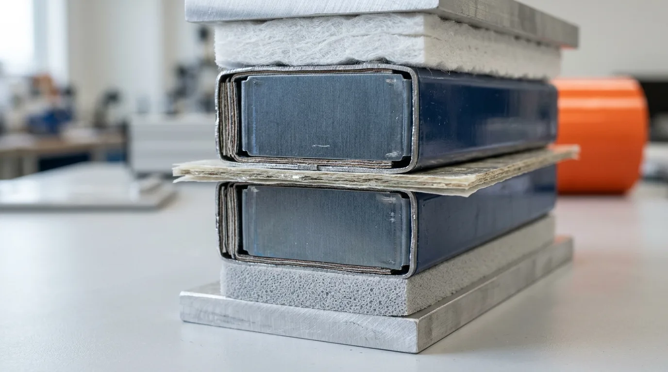
A working inter-cell stack-up: rigid mica for the fire wall, foam for tolerance and compression, ceramic fiber for the module lid. Rarely one material alone.
Where Each Material Sits in the Pack
Placement is where most thermal runaway containment designs succeed or fail, because the same material behaves differently at four locations:
- Between adjacent cells. The highest heat flux and the smallest available thickness. A thermal runaway barrier here is usually rigid mica, thin ceramic fiber, or aerogel where mass matters. It must cover the full facing area — a barrier that leaves the top 10 mm of the cell face exposed gives the flame a path around it.
- Between module and pack structure. Here the requirement is often insulation plus mechanical isolation. Silicone foam or a foam-cored composite does both; a rigid sheet alone transmits shock loads into the cell stack.
- At the pack lid and enclosure. Fire barrier plus seal. Mica or ceramic for the barrier, a low-compression-set foam gasket for the IP rating, and a design that keeps the two functions in separate parts.
- Along the vent path. The ejecta has to leave the module without passing another cell. Intumescent or ceramic-lined vent channels, plus pressure relief sized for the gas volume, turn a trapped fire into a directed one.
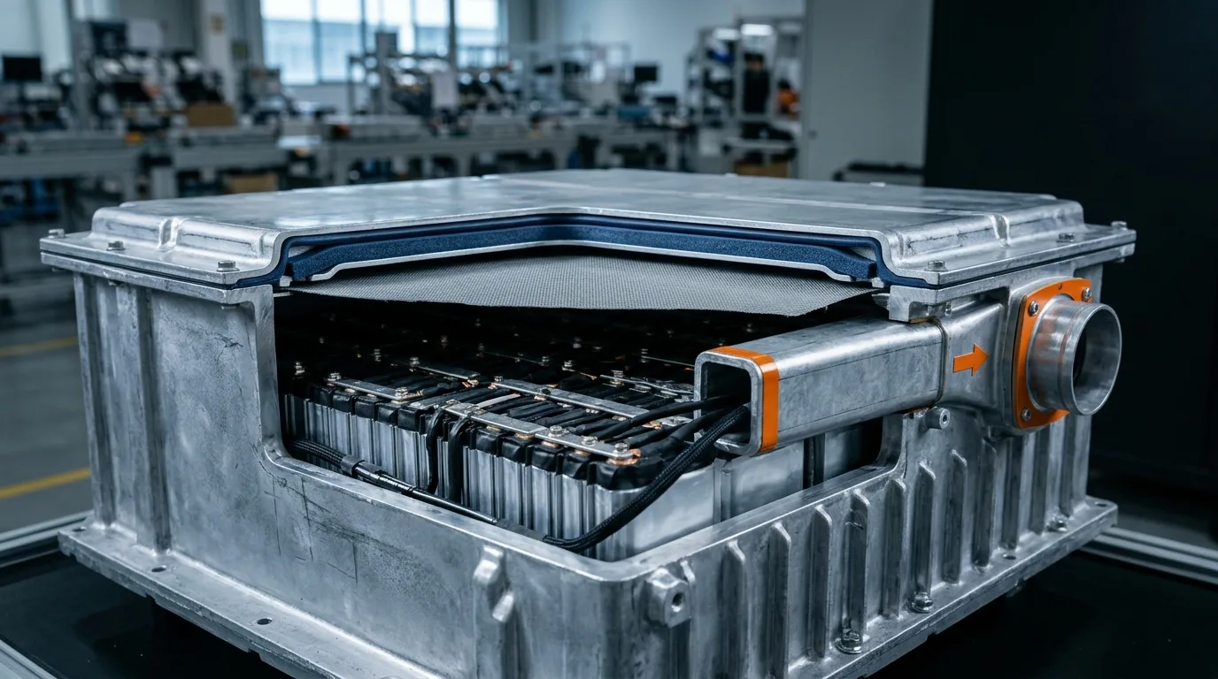
Containment at pack level is a routing problem: barrier at the lid, gasket at the groove, and a vent path that never runs past another cell.
What the Tests and Standards Actually Require
Containment claims are only as good as the test behind them. Four documents come up repeatedly — the table below carries six rows, counting both editions of GB 38031 and its cell-level test separately — and they ask different questions.
GB 38031. The 2020 edition introduced a thermal propagation test with an escape-window logic: after thermal runaway of a single cell, the pack must not catch fire or explode for at least five minutes, and must give a thermal event warning so occupants can leave (Obelis summary of GB 38031-2020). The 2025 revision moves the bar from escape time to containment. GB 38031-2025 took effect on 1 July 2026, with reworked thermal-diffusion testing that clarifies temperature requirements, observation time and vehicle test conditions, plus two new tests: a bottom impact, and a safety test after fast charging (gov.cn / Xinhua).
Three details decide what a barrier has to do, and they are easy to lose in the press summaries. First, the alarm deadline was kept, not traded away: clause 5.2.7 still requires a thermal-event alarm no later than five minutes after the trigger cell goes into runaway, plus a pack-level demonstration that smoke does not endanger the cabin from before that alarm until five minutes after it. Second, the fire criterion now holds through a defined observation period rather than a five-minute escape window — clause C.5.3.8 ends the test only when every monitoring point is at or below 60 °C, and not before two hours. So the two hours is a floor, and 60 °C is the settling temperature the pack has to come back to before the test is allowed to end — a number you can write into a barrier specification, which no pass/fail label gives you. Third, the level matters. Cells that charge from 20 % to 80 % SOC in 15 minutes or less must survive 300 fast-charge cycles followed by an external short circuit with no fire and no explosion — a cell-level requirement (5.1.7, tested per 8.1.8) — while the bottom impact is a pack, system or vehicle test (5.2.16).
What changed for a materials engineer is not the alarm deadline but what has to be true around it: five minutes of grace before fire became two hours of no fire, with the pack required to settle back under 60 °C — one of the main drivers of thermal barrier demand today.
UL 94. The material-level flame rating. V-0 is the usual gate for anything inside a pack, and it is a small-scale test on a coupon — two ten-second applications of a vertical Bunsen flame to a 125 × 13 mm specimen, at a defined thickness, not how a material behaves against a cell vent jet. Our UL 94 V-0 vs VTM-0 comparison covers what the ratings do and do not prove.
UL 9540A and NFPA 855. For stationary storage rather than vehicles, but the logic transfers. UL 9540A is the test method for evaluating thermal runaway fire propagation in battery energy storage systems, and it is now in its sixth edition — published 13 March 2026, effective 1 January 2027 — which reworks the installation-level test around a large-scale fire scenario that assumes a post-deflagration condition, in line with the new Annex G.11 of the 2026 edition of NFPA 855 (UL Solutions on UL 9540A Ed. 6). The fifth edition, published a year earlier, had added clearer criteria for cell-to-cell propagation and high-temperature test methods for several battery chemistries (UL Solutions, April 2025). UL 9540A remains the only consensus standard explicitly referenced in NFPA 855 for large-scale fire testing. NFPA 855 is the installation standard that consumes those results (NFPA 855).
Cell-level abuse tests. Nail penetration, external heating and overcharge are how a trigger cell is created in a propagation test. Ask which trigger method the test used; a barrier that passes with an external-heater trigger may fail with a nail, because the ejecta pattern differs.
| Document | The question it asks | Where it applies |
|---|---|---|
| GB 38031-2020 | Does the pack give warning and hold off fire for 5 minutes after a cell runs away? | China, EV traction batteries |
| GB 38031-2025 — pack / system (in force 1 July 2026) | Does the pack avoid fire and explosion through the observation window (at least 2 h, ending when every monitoring point is ≤60 °C), and survive a bottom impact? | China, EV traction batteries |
| GB 38031-2025 — cell (in force 1 July 2026) | Does a fast-charge cell survive 300 fast-charge cycles followed by an external short circuit, with no fire or explosion? | China, EV traction batteries |
| UL 94 (V-0) | How does this material behave in a small vertical flame test? | The material itself, any market |
| UL 9540A | How does this battery technology propagate — cell, then module, then the installation-level large-scale fire test (unit level reserved under Ed. 6)? | Stationary storage, US/Canada |
| NFPA 855 | How must the installation be spaced, protected and vented? | Stationary storage, US |
Specification Checklist: What to Demand Before You Approve a Sample
Ten items, in the order that saves the most time. Every one of them is a question a thermal runaway barrier supplier should be able to answer with a document, not a brochure:
- Through-thickness temperature curve, not just a conductivity number. Ask for the far-face temperature versus time under a defined flame or heater load, at the thickness you will actually use.
- Decomposition and structural-failure temperature, with the test method named.
- Dielectric strength in kV/mm, plus volume resistivity after humidity conditioning.
- Compression set and compression force deflection if the part is foam. Compression set above about 5% means the seal and the retention force drift over life.
- Density and areal weight, so the energy-density penalty is a line in your model rather than a surprise.
- Flame rating with thickness. A V-0 rating at 3 mm does not transfer to 1 mm.
- Outgassing and low-molecular siloxane content if the barrier sits near optical, sensor or high-voltage components.
- Cut and converted form: tolerance, edge quality, dust control, and whether the supplier can deliver the part die-cut rather than as a roll.
- Aging data — thermal cycling and humidity, ideally on the assembled stack rather than on coupons.
- The test report behind the claim, referencing the standard and the trigger method.
Where a Materials Supplier Actually Changes the Outcome
Two things go wrong in containment projects that no datasheet catches. The first is a barrier that is correct in principle and impossible to build: a 0.4 mm mica composite with a ±0.15 mm tolerance, hand-placed, at automotive volumes. The second is a stack-up where the fire barrier, the compression pad and the enclosure seal are sourced from three suppliers who each optimise their own part and nobody owns the interface.
That is the argument for converting and material supply from one place. ZIITEK's contribution to this problem is deliberately narrow and worth stating precisely: we do not manufacture mica or aerogel. We make the silicone foam side of the stack — Z-FOAM®800, UL 94 V-0 and IP68, −40 to +200 °C, compression set ≤5% — the thermally conductive materials for the heat path that has to stay conductive, and the die-cut converting that turns all of it, including customer-supplied mica and ceramic, into parts that fit the fixture. The one-stop battery thermal conduction, sealing and heating approach explains how those families are specified together, and the IATF 16949 system behind it matters if the pack ships into an automotive program.
If you are mid-design, send the stack-up drawing and the target test condition: we will tell you which layer we can own, which layer you should keep sourcing elsewhere, and what the interface between them needs to look like.
FAQ
Does a thermal pad stop thermal runaway?
No, and using one as a barrier makes propagation faster. Pads and gap fillers are formulated to minimize interfacial thermal resistance between a cell and a cold plate. Between two cells, the same material becomes a heat bridge. Barriers need low thermal diffusivity and flame stability; thermal interface materials are specified for the opposite job.
How thick should an inter-cell barrier be?
Thickness is a function of the trigger energy, the cell format and the time you have to buy, so no universal number exists. In practice, mica composites run 0.3–2 mm, ceramic fiber 1–5 mm, and aerogel blankets 1–3 mm, with aerogel buying the most delay per millimetre. Specify against a measured far-face temperature curve at your thickness rather than against a nominal conductivity.
Is UL 94 V-0 enough for a battery barrier?
It is necessary and not sufficient. V-0 is a small-scale vertical flame test on a coupon; it says nothing about resistance to a venting cell's particle jet, about through-thickness heat transfer, or about mechanical survival at 800 °C. Treat V-0 as an entry ticket and require propagation-level testing on the assembled module.
Can thermal runaway be prevented entirely?
Not at cell level, and claims otherwise should be read carefully. What a well-designed pack is designed to achieve is non-propagation, under a defined trigger and observation window: a single cell fails, the pack vents, and the event stays contained. That is what GB 38031-2025 asks for in China — no fire and no explosion, with the pack required to cool back under 60 °C and stay observable for at least two hours — and it is a materials and architecture problem before it is a chemistry problem.