Epoxy Potting Compound: A Guide for Electronics
Choose a potting compound by Tg, CTE and W/m·K, not by color. How epoxy, polyurethane and silicone differ, how to pour without voids, and what UL 94 proves.
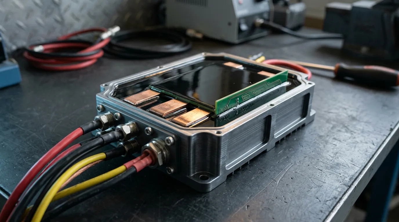
This guide is for the engineer who has to specify a potting compound, not just buy one: how the families differ, which numbers decide the design, how the pour goes wrong, and the spec to send a supplier.
What a potting compound actually does
Pour a two-part epoxy potting compound into a housing and let it cure, and the assembly inside stops behaving like an assembly. Connectors, busbars, solder joints and ceramic capacitors become one encapsulated block that a vibration table, a salt-fog chamber and a 4 kV hipot test can no longer pick apart. That is the job, and not the job a conformal coating does.
A conformal coating is a film measured in microns: it follows the board's topography and protects against moisture, but adds no structure. Potting fills the volume, replacing the air around components with a dielectric solid, carrying heat into the housing wall and locking the assembly against shock. Encapsulation is the same act done in a mold rather than a housing; supplier catalogs blur the two, the test standards do not.
Four duties come with the pour, and they pull against each other:
- Dielectric isolation. Air is a poor insulator once it ionizes; a solid wall of filled resin is not. This is why high-voltage assemblies are potted at all, and why the insulator and isolation layer under a MOSFET matters as much as the compound above it.
- Moisture and chemical barrier. A void-free pour keeps condensation, cleaning solvents and battery electrolyte away from the joint.
- Mechanical support. It spreads shock across the whole volume instead of a few solder fillets.
- Heat path. Filled systems conduct heat to the housing; unfilled ones do not, and are chosen for electrical or mechanical reasons only.
The conflict is that what makes a compound good at the first three duties — filler loading, high modulus, strong adhesion — also makes it stiff, and stiffness cracks boards. Most of the engineering in this category is managing that trade. The rest of the potting and encapsulation family is mapped from the hub.
Epoxy, polyurethane, silicone: what actually differs
Three chemistries cover nearly every potting application, and the differences that matter on the line are not in the marketing table.
| Family | Hardness after cure | Service range | Thermal conductivity available | Where it fails |
|---|---|---|---|---|
| Epoxy | Rigid, Shore D 70 and above | −65 to +180 °C | 1.2–3.1 W/m·K in filled grades | Cracks under CTE stress; not reworkable |
| Polyurethane | Soft to semi-rigid | −65 to +125 °C | Low unless heavily filled | Polyester grades hydrolyze in hot, humid service |
| Silicone | Shore A 25 to Shore D 85, plus soft gels | −65 to +200 °C | 1.0–4.0 W/m·K in filled grades | Low tear strength; adhesion needs a primer |
The cure behavior described here is Henkel's, from their potting and encapsulating selector guide: epoxies and polyurethanes typically gel in one to three hours with a 24-hour full cure, their one-part and UV-cure silicones are limited to shallow sections, and epoxy is the only family pairing a high glass transition with a rigid cured state. Depth limits are product-specific rather than a property of the family — the two-part silicones at the end of this guide are poured as bulk castings — so read that line on the datasheet you are actually buying. The hardness and conductivity bands in the table are typical ranges for filled grades across published datasheets rather than figures from any single document — the STYCAST sheet below is one point inside the epoxy band, and ZIITEK's own TIE280 grades sit at its lower end.
Epoxy is the structural choice: it bonds to the housing, resists solvents and takes the heat. Polyurethane is the shock choice: it flexes with the assembly, at the cost of a ceiling near 125 °C and moisture sensitivity during cure. Silicone is the stress choice: it accommodates differential expansion without loading the solder joints, but it is soft and needs surface preparation to stay bonded.

Why the epoxy potting compound is the default in power electronics
Ask for a potting compound and you will usually be quoted an epoxy — not because it conducts heat best, but because of the glass transition temperature and what happens on either side of it.
Below Tg, a cured epoxy is glassy: low coefficient of thermal expansion, high modulus, dimensional stability. Above Tg, the same material expands several times faster and its modulus collapses. A published filled encapsulant shows the size of that step: a Henkel STYCAST 2850KT datasheet quotes CTE of 23 µm/m·°C below Tg and 102 µm/m·°C above it, Tg of 137 °C by DMA, thermal conductivity 3.1 W/m·K and Shore D 91. Two lessons sit in that data: the CTE you design with is the sub-Tg value only if the joint stays below Tg, and an operating range of −40 to +175 °C does not mean the compound stays rigid at 175 °C.
Tg is not a fixed property of a resin. In Henkel's study of Tg and CTE in semiconductor encapsulants, raising cure temperature from 130 °C to 175 °C moved Tg from 117 °C to 146 °C and CTE from 22.9 to 24.3 µm/m·°C on the same material. The paper's more useful point is that Tg is a band, not a point, and that DSC, TMA and DMA return different numbers for the same specimen — the STYCAST datasheet shows 137 °C by DMA against 127 °C by TMA. "Tg 150 °C" in a quotation means little until you know the method.
Epoxy adheres to FR-4, aluminum and most molding compounds without a primer, resists cleaning solvents, and its low sub-Tg CTE sits close to the metals it bonds. The cost: that same rigidity transfers CTE mismatch into the weakest thing in the assembly. On a board with large multilayer ceramic capacitors or a heavy busbar, a rigid pour can crack the part it was meant to protect.
The numbers on the datasheet that decide the design
Seven lines carry the decision. Each has a test method behind it, and a number without the method is not a specification.
Thermal conductivity, W/m·K. Read it as a material property, not a joint figure. The usual method is steady-state through a thin specimen, ASTM D5470, and it says nothing about bond-line thickness or contact resistance at the housing wall: a 3 W/m·K compound poured 8 mm thick is a worse heat path than a 1.5 W/m·K compound poured 2 mm thick. The W/m·K explainer covers how those numbers are obtained.
Dielectric strength, kV/mm. Measured to ASTM D149 at a stated ramp rate and thickness; it falls sharply once there are voids. A value taken on a 1 mm plaque is not a design value for a 4 mm wall.
Tg, with the method. DMA to ASTM D7028, TMA, or DSC — the three disagree by design. Ask for DMA if the joint sees fast thermal transients, TMA if dimensional change is what you care about.
CTE below and above Tg, in µm/m·°C. Two numbers from one TMA run (ASTM E831), never one. If the application can reach Tg — a motor housing at 150 °C, an inverter in a hot bay — the second number governs the stress.
Hardness, with the scale. Shore D, Shore A and Shore 00 are not convertible; durometer hardness is ASTM D2240. A "Shore 65" claim means nothing until you know which scale.
Pot life and gel time, at a stated temperature and mass. ASTM D2471 measures gel time and exotherm on a small cup; your 3 kg batch will not behave the same way.
Flammability and thermal index. UL 94 rating and UL 746 recognition, both covered below.
Three grades of one filled epoxy family show how that looks in a catalog:
| Grade | Thermal conductivity | Hardness | Cure schedule |
|---|---|---|---|
| TIE280-12AB | 1.2 W/m·K | Shore D 85 | 24 h at 23 °C or 3 h at 70 °C |
| TIE280-15AB | 1.5 W/m·K | Shore D 75 | 24 h at 23 °C or 3 h at 70 °C |
| TIE280-25AB | 2.5 W/m·K | Shore D 85 | 24 h at 23 °C or 3 h at 70 °C |
The trade in miniature: the middle grade is softest; the top conducts twice as well as the bottom and is among the hardest. Filler loading buys conductivity and dimensional stability, and pays for it in modulus and viscosity.
Process: mixing, degassing, pouring, curing
Mix by weight, not by eye. A 1:1 ratio is usually specified by weight; by volume it is 1:1 only if both components have the same density, and filled resins rarely do. Off-ratio mix leaves under-cured patches that measure fine on the bench and turn tacky in the field. Mix for the full time, scrape the cup walls, and mix what you can pour inside the pot life.
Degas before you pour. Mixing folds air into the compound, and the pour traps more under components and in connector cavities. A vacuum chamber held until the froth collapses removes most of it. Skipping this is the most common cause of voids — and voids are invisible once the housing is closed.
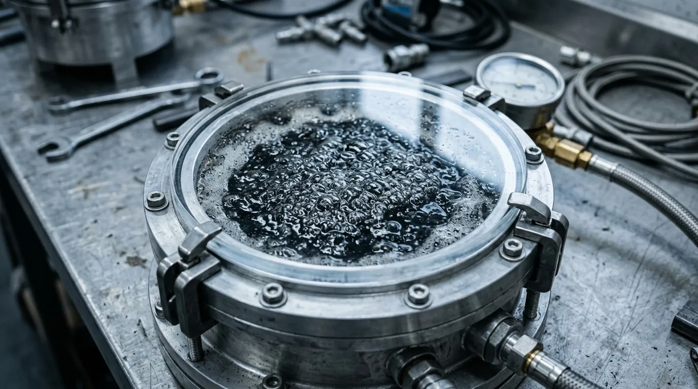
Control the pour temperature. Warming the housing and board to 30–40 °C drops viscosity enough for the compound to climb around components and wet surfaces. Pour into one corner and let the level rise; pouring across the middle bridges components and traps air beneath them.
Respect exotherm in deep sections. Epoxies can fill deep castings, but a large mass in an insulated housing generates its own heat and the reaction accelerates. A compound with a 90-minute pot life in a 100 g cup can gel in a fraction of that time in a 2 kg casting, scorching in the center. For thick sections, ask for a slower catalyst rather than pouring colder.
Cure on a schedule, and cure fully. Room temperature for 24 hours and 3 hours at 70 °C are both real schedules for the same family, but they do not produce identical material: the warmer cure reaches a higher conversion and, as the Henkel data shows, a higher Tg. Nothing should be thermal-cycled before it is fully cured.
Dispensing hardware follows the same logic as gel and gap-filler dispensing: material and pump have to be chosen together.
Failure modes that appear after cycling
These defects rarely appear in first-article inspection, only after hundreds of cycles at voltage.
Voids and partial discharge. A void inside a high-voltage pour is a gas pocket in a high-field region. Partial discharge starts in it, erodes the resin, and the path to failure is a tracking channel through what was meant to be the insulation. X-ray, ultrasonic C-scan, or a destructive cross-section of a sacrificial unit is how you find out whether degassing worked.
Delamination at the interface. The pour separates from the housing wall or a component body. Usual causes: mold release or flux residue, a pour too cold to wet, or stress at a sharp corner.
Cracking from CTE mismatch. The signature is a hairline crack running from the corner of a large ceramic capacitor or a busbar edge. Rigid epoxy, a big CTE step and a fast cool-down concentrate stress at the stiffest interface; softening the compound, slowing the ramp or adding a compliant layer all attack the same mechanism.

Filler settling. Heavily filled systems can settle during a long pot life, especially in a tall housing, so the top of the casting ends up with lower conductivity and a different CTE. Cured epoxy also does not come out, so a repair decision belongs before the pour.
What the compliance marks do and do not cover
Three marks appear on every potting datasheet, and each is narrower than buyers assume.
UL 94 V-0 is a specimen burn rating. Under the 50 W vertical burn test, a V-0 specimen must stop burning within 10 seconds after each of the two flame applications, no more than 50 seconds across ten applications, stop glowing within 30 seconds after the second, and drip nothing that ignites cotton. The criteria are published by UL Solutions. What it does not tell you: how your housing behaves, whether your creepage is adequate, or what the assembly does in a fire. The V-0 versus VTM-0 distinction matters when the compound is thin.
UL 746 and relative thermal index. UL 746 covers polymeric materials in electrical equipment, and the relative thermal index derived from it speaks to long-term thermal aging rather than short-term tolerance. A 150 °C RTI is an extrapolation from long-term oven aging, which is stronger evidence than surviving an oven soak — but it is not a decade of field data.
IPC-CC-830B qualifies electrical insulating compounds for printed wiring assemblies. Its scope is conformal coating — a thin film — and its test board reflects that. Its scope statement is routinely cited as if it qualified a cast potting, and it does not. If a supplier offers IPC-CC-830B for a 5 mm pour, ask what test actually covers the pour.
RoHS and REACH are substance obligations, not performance claims. The RoHS directive restricts lead, mercury, cadmium, hexavalent chromium, the brominated flame retardants and four phthalates; REACH adds the SVHC declaration duty. Ask per grade, with a date, not per product family.
A potting spec you can send to a supplier
Ten lines turn this into a request a supplier can answer without a meeting:
- Chemistry and target hardness, with the scale named.
- Thermal conductivity target and the heat path it serves — component area, bond-line thickness, housing material.
- Tg and both CTE values, with the measurement method you will accept.
- Dielectric strength at your actual wall thickness, not at 1 mm.
- Continuous service temperature and the RTI behind it.
- Pot life at your shop temperature and batch mass.
- A cure schedule your oven or line can actually run.
- UL 94 rating and the UL file number for the grade.
- RoHS and REACH declarations dated within the last year.
- Shelf life, storage condition and rework policy.
For the rigid end of that spec, ZIITEK's TIE280-AB epoxy family covers the three grades in the table above: 1.2 to 2.5 W/m·K, 1:1 by weight, Shore D 70 and above, cured 24 hours at room temperature or 3 hours at 70 °C, for PCBA and power-module encapsulation, sensors and EV battery packs. Where the assembly cannot take a rigid pour — large ceramics, long busbars, a housing with a different expansion rate — the TIS680 silicone series covers 1.0 to 3.5 W/m·K, Shore A 65 to Shore D 85 plus soft gels, over −50 to +200 °C. Grade lists are on the epoxy potting compound product page.
Potting is one of the few decisions in a power assembly that cannot be revisited after the first production run. Getting the family right, then the seven datasheet numbers, then the process, is cheaper than getting any one of them wrong.
Common questions
What Tg does a potting epoxy need?
Above the highest temperature the joint reaches in service, with margin for cure exotherm and a hot-soak fault. For a module running at 105 °C, a Tg of 130 °C or more keeps the joint glassy, where the datasheet CTE and modulus apply.
Why did my potted board crack after thermal cycling?
Almost always CTE mismatch amplified by a rigid compound. The resin expands several times faster above Tg than below it, the copper and ceramic inside expand at their own rates, and the interface takes the difference. Find where the crack starts — the corner of the largest ceramic, or a busbar edge — then soften the compound, slow the ramp, or add a compliant layer there.
Is UL 94 V-0 enough for a high-voltage assembly?
No. V-0 is a small-specimen burn rating and says nothing about partial discharge, tracking or creepage in your housing. Qualify the finished assembly — hipot, partial discharge and thermal cycling — and treat V-0 as one input among several.