Thermally Conductive Electrical Insulators (Sil-Pad Type)
Choosing thermally conductive electrical insulators: sil-pad type pads vs mica, ceramic and grease stacks, judged by breakdown voltage, W/m·K, thickness and UL.
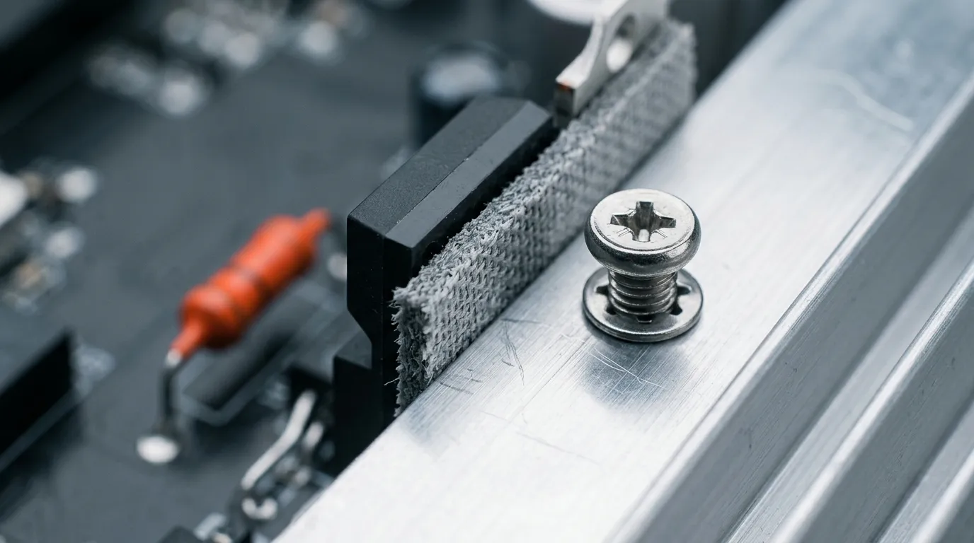
A thermally conductive electrical insulator has to do two jobs at once: move heat out of a power semiconductor, and stop current from taking the shortcut through the heatsink. The sil-pad type — a glass-fiber-reinforced silicone pad — is the default answer for most TO-220, MOSFET and IGBT designs, and choosing one is about four numbers, not one: breakdown voltage, thermal conductivity (W/mK), thickness, and hardness. Each constraint pulls against the others, so the material that "wins" on a single spec is usually the wrong part. This guide walks through the physics, the alternatives (mica, ceramic washers, grease-plus-insulator stacks), and the spec-by-spec method engineers actually use to lock in a part.
What Makes a Thermally Conductive Electrical Insulator Different
A normal thermal pad conducts heat and does not care much about electricity — most silicone pads are not rated as insulators. A thermally conductive electrical insulator is the opposite discipline: the same sheet must carry heat efficiently while blocking electrons, which is a harder materials problem than it sounds.
It works because of a two-phase structure. Ceramic particles — aluminum oxide (alumina), aluminum nitride, boron nitride — form a percolating network that conducts phonons (heat) through the sheet, while the silicone or polyimide matrix surrounding them is a genuine electrical insulator. Heat travels along the filler network; electrons cannot hop the polymer barrier between particles. The result is a material with a thermal conductivity of roughly 1–2 W/m·K and a dielectric strength measured in kilovolts per millimeter — dielectric strength being the voltage gradient the material withstands before it breaks down and arcs through.
The concept boundary matters here, because the English word "insulator" causes endless confusion in datasheet searches. A thermal insulator (fiberglass batt, aerogel, polyurethane foam) is the opposite product — it blocks heat. A thermally conductive electrical insulator conducts heat and blocks current. If you are looking for "insulating thermal pad" or "electrical insulation thermal pad," you want the second family. The two share vocabulary, zero applications.
What "Sil-Pad Type" Means: Glass-Fiber-Reinforced Insulators
"Sil-pad" started as a Bergquist trademark in the 1970s for a silicone pad reinforced with woven glass fiber, and it has long since become the generic name for the whole category — the way "Kleenex" became the word for tissue. Today any glass-fiber-reinforced silicone insulator is called sil-pad type, and the product families from Laird, Henkel/Bergquist, Fujipoly and smaller specialty houses all follow the same recipe: thermal interface material suppliers reinforce a ceramic-filled silicone sheet with a fiberglass cloth or a polyimide (Kapton®-class) film in the middle.
Why the reinforcement? Unreinforced silicone is soft enough that a rough heatsink edge, a burr on a stamped bracket, or a sharp component lead can cut through it under clamp pressure — and a cut-through is a pinhole, and a pinhole is where the breakdown voltage silently collapses. The glass cloth or polyimide layer in the middle of the sandwich gives the pad cut-through resistance: the silicone still conforms to surface roughness, the ceramic filler still conducts heat, but a sharp point now has to punch through woven glass or a polyimide film before it can short the device. That mechanical backbone is the entire point of the sil-pad construction, and it is why reinforced pads can be made thinner (0.15–0.5 mm is a typical band) than unreinforced gap pads.
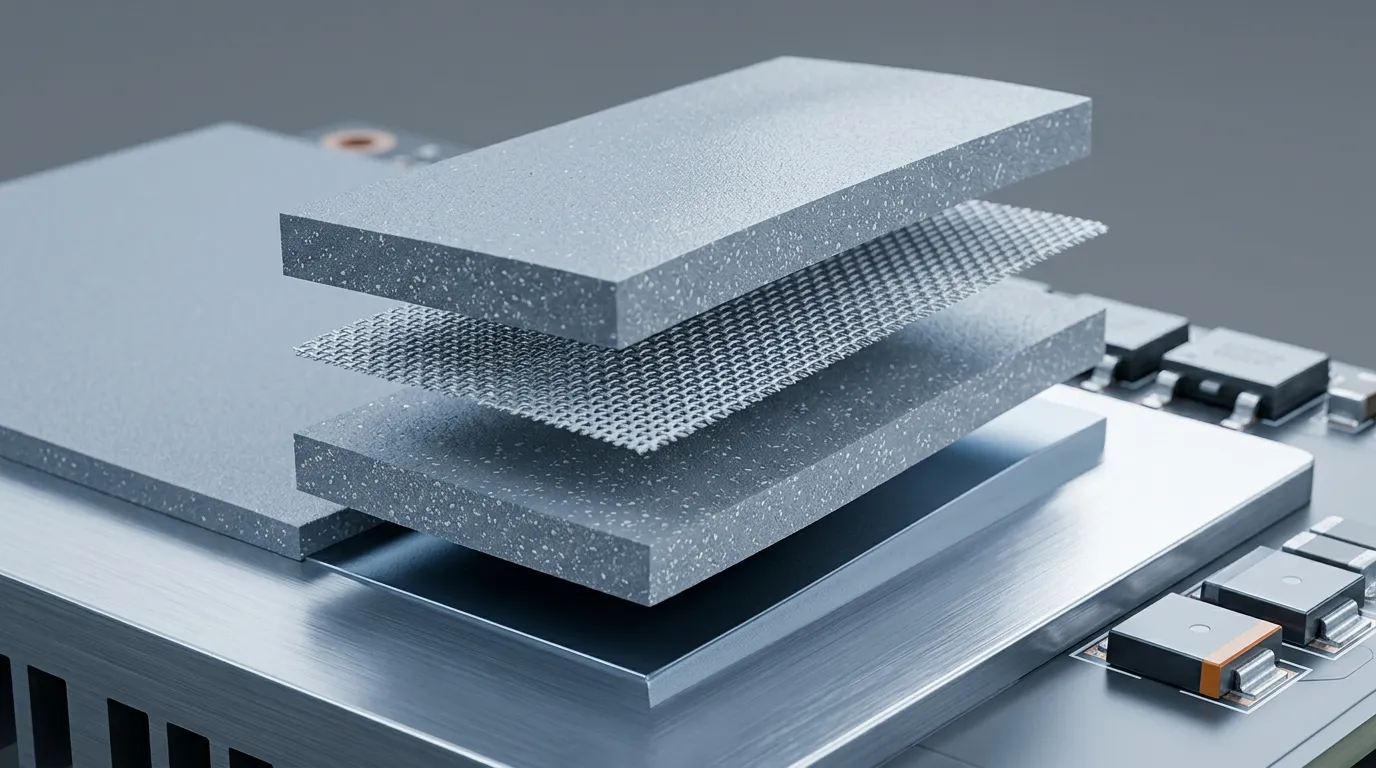
Sil-pad construction: ceramic-filled silicone on both faces, woven glass fiber (or polyimide) in the middle for cut-through resistance.
Sil-Pad Type vs. Mica, Ceramic Washers, and Grease-Plus-Insulator Stacks
The sil-pad pad is not the only way to insulate a power device from its heatsink, and it is not always the right way. Three older alternatives still show up in production: mica washers, ceramic washers, and a thin insulator sheet coated on both sides with thermal grease. They are the same decision, different trade-offs:
| Option | Thermal conductivity | Breakdown / dielectric strength | Assembly behavior | Typical cost |
|---|---|---|---|---|
| Mica washer | ≈0.5 W/m·K (muscovite) | High per sheet, but pinhole- and crack-sensitive | Brittle; needs grease both sides; fragile in handling | Lowest |
| Ceramic washer (alumina) | ≈20–30 W/m·K | Very high; rigid and unforgiving | Hard, brittle; requires flat, burr-free surfaces | Low–medium |
| Grease + thin insulator sheet | Depends on the sheet (polyimide ~0.1–1 W/m·K) | High if the sheet is sound | Two or three extra assembly steps; grease migration risk | Low, plus labor |
| Sil-pad type (glass-fiber reinforced) | 1.0–1.6 W/m·K | 1500–6000 VAC typical | Compressible; die-cuts to shape; no grease needed | Medium |
Mica is the classic answer — thin, cheap, and electrically strong — but it is brittle and must be greased on both faces to fill the air gaps between its surface and the device/heatsink, because its own surface finish is far from optical; mica's electrical and thermal properties are excellent as bulk values, but the practical washer is pinhole- and crack-sensitive in handling. Two grease applications, two chances for contamination, and the grease itself can pump out under thermal cycling.
Ceramic washers conduct heat far better than anything else in this table — alumina at roughly 25 W/m·K — which is why they persist in high-power modules. The catch is mechanical: a ceramic washer cannot conform. Any warp in the device or heatsink becomes a point load, and ceramic cracks under it. They also need grease and a carefully flat stack, so the assembly cost is real.
The grease-plus-insulator stack (typically a polyimide or mica sheet coated with thermal paste on both sides) is what most service engineers picture when they hear "insulator." It works, and it is cheap per unit, but it is the most labor-intensive option and the most variable, because bond-line thickness and grease coverage are operator-dependent.
The sil-pad type trades the top-end thermal conductivity of ceramics for three engineering wins: it compresses to absorb stack-up tolerance (no point loading, no cracking), it does not need grease (one part instead of three), and it can be die-cut to the exact footprint of the device. That is why, for the majority of TO-220/TO-247, MOSFET and IGBT mounting jobs on power supplies, inverters and motor drives, reinforced pads have replaced mica as the default.
Five Numbers That Decide an Insulator: W/m·K, Breakdown Voltage, Thickness, Hardness, UL
When a thermally conductive electrical insulator datasheet is in front of you, five numbers decide the part. Go through them in this order, and treat any datasheet that is missing one of them as incomplete.
1. Dielectric breakdown voltage (and the test conditions). This is the insulator's reason to exist. Breakdown voltage is quoted either as an absolute value in volts AC (e.g., 3000–6000 VAC) or as dielectric strength in kV/mm. The two are not interchangeable — a 0.25 mm sheet with 20 kV/mm dielectric strength withstands about 5 kV, so compare absolute withstand voltages at the same thickness. Always check the test method and the sample thickness, because breakdown voltage scales with thickness and the datasheet value is measured on a specific thickness. For mains-connected power supplies, a common engineering rule of thumb is to spec 2–3× the peak operating voltage plus margin for transients.
2. Thermal conductivity (W/m·K) and thermal impedance. W/m·K is a bulk material property, measured for pads per ASTM D5470. The number that matters for the junction temperature, however, is the thermal impedance (°C·in²/W or °C·cm²/W) at the pad's real compressed thickness and clamp pressure — usually quoted at 50 psi or 10 psi. Two pads with identical W/m·K can differ by 30% in impedance if one is thicker or stiffer. The distinction between thermal impedance versus thermal resistance is exactly where datasheet comparisons go wrong, so match the impedance number, not the marketing blurb.
3. Thickness. The datasheet thickness is the uncompressed value; what matters in the assembly is the compressed layer thickness (CLT) under the real clamp load. A pad 10–30% thicker than the nominal gap is the standard starting point, so it compresses to fill the gap with positive contact pressure. Thicker insulation also means higher breakdown margin but higher thermal impedance — the two move together, which is why insulator selection is a balance, not a maximization.
4. Hardness (Shore 00) and clamp force. Softer pads conform better and put less force on the device, which protects fragile packages and thin PCBs; harder pads hold dimensional tolerance and cut cleaner in die-cutting. The insulator's hardness interacts with the mounting torque to decide the actual compressed thickness — the same reason the thermal pad thickness and compression guide treats thickness and hardness as a pair.
5. UL 94 flame rating and compliance paperwork. Power supplies and automotive electronics almost always require UL 94 V-0 rated materials. Verify the rating on the UL Yellow Card for the specific grade — not on the datasheet's marketing line. For EU-bound products, RoHS and REACH declarations are table stakes, and automotive programs add IATF 16949 supply-chain certification. A supplier that cannot produce the certificates on request is a supplier to drop from the shortlist.
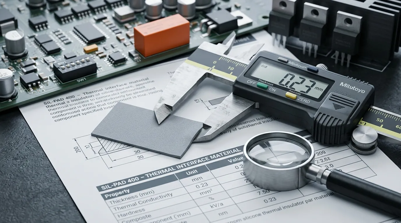
The five-number pass: breakdown voltage, W/mK, thickness, hardness and UL rating — read in order, against the assembly's real conditions.
Why Insulator W/mK Stays Low: The Conductivity–Breakdown Tradeoff
Newcomers to insulator selection routinely reject a perfectly good 1.5 W/m·K pad because "the gap filler next to it does 8 W/m·K." The gap filler is not competing with the insulator, and the insulator is not a worse product — it is solving a constrained problem.
Thermal conductivity in a filled polymer comes from the volume fraction of ceramic filler: more filler, more conductive pathways. But every filler particle is also an inclusion inside the insulating matrix, and at high filler loadings the particles crowd into near-touching chains that shorten the electrical breakdown path through the sheet. The classic engineering history of thermal interface materials is exactly this fight: every gain in W/m·K is a step toward the point where the material stops being an insulator. Add the glass reinforcement — which is itself thermally neutral — and you see why the sil-pad family lives in the 1–2 W/m·K band while an unreinforced, non-insulating silicone pad can reach 16 W/m·K.
The practical consequence: judge a thermally conductive electrical insulator by whether its impedance and breakdown voltage meet the design target, not by whether its W/m·K is the biggest number on the shelf. If a design genuinely needs both high thermal conductivity and galvanic isolation at high power, the answer is usually not a better pad — it is a different thermal architecture: ceramic (AlN) substrates, or moving the isolation to the system level with a DC-DC barrier, which is a separate design discussion. Within the pad family, what W/m·K really measures is worth reading before you benchmark grades against each other.
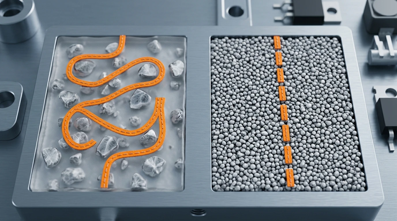
Every gain in W/m·K shortens the electrical breakdown path: insulator grades cluster at 1–2 W/m·K precisely because of this constraint.
Mounting and Assembly: Where Insulators Fail in Practice
Most insulator field failures are not material failures — they are assembly failures. The material was fine; the installation killed it.
Cut-through is the #1 killer. A burr on a stamped heatsink, a sharp corner on a TO-220 tab, or a rough PCB edge can slice through a thin pad at clamp pressure. This is precisely what the glass-fiber reinforcement in a sil-pad type pad is for, but it only works if the pad covers the hazard: check that the pad extends beyond the device footprint and the mounting hole, and deburr mating surfaces. Once a cut-through pinhole exists, breakdown voltage drops to near zero and the failure is intermittent until the device shorts.
Torque discipline. The screw torque that clamps the device also sets the compressed thickness of the pad. Over-torquing squeezes the pad to a fraction of its spec thickness — higher breakdown margin than designed? No: it can displace the silicone, thin the dielectric layer, and stress the package. Under-torquing leaves the pad under-compressed with air gaps, which raises impedance. Follow the assembly drawing's torque spec, and remember that a soft pad (low Shore 00) compresses more per unit torque than a stiff one — the same torque gives different CLT for different pads.
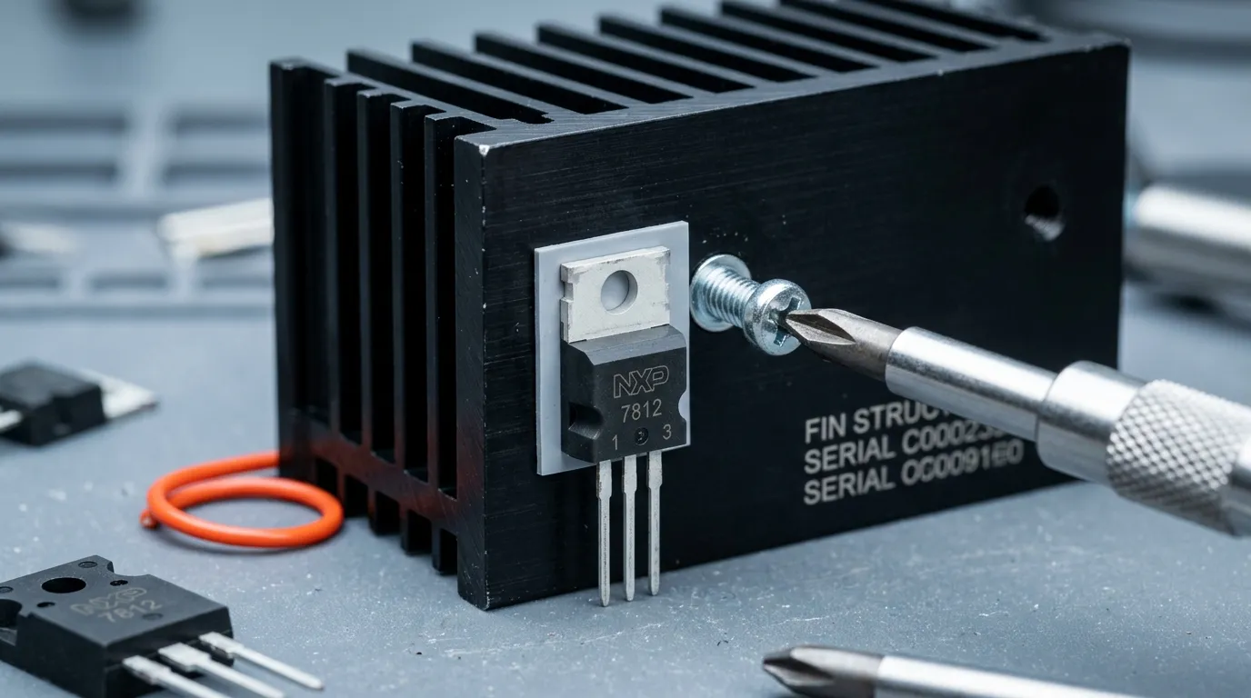
The assembly is part of the spec: torque sets compressed thickness, and a burr on the heatsink can cut through an unreinforced pad.
Edge condition and die-cutting. Pads die-cut to shape must have clean, burr-free edges: a ragged edge from a dull die leaves fiberglass whiskers that can wick moisture or provide a tracking path under humidity. When the insulator must bridge a pocket or wrap a lead frame, specify the drawing, not an approximate rectangle — suppliers including ZIITEK offer custom die-cutting to the exact footprint.
Thermal interface on both faces. Unlike grease, a pad relies on contact pressure, not wetting, so both faces need the pad's rated compression. If the device side is a lead-frame with raised leads, the pad must be thick enough to conform over the topology, or the contact is point-to-point and the impedance number on the datasheet is fiction.
Specing Insulators for TO-220, MOSFET and IGBT Designs
Putting the method together, here is what a real selection looks like for the three most common power electronics cases.
TO-220 and TO-247 through-hole packages are the classic sil-pad application. The device tab is electrically live (often at full bus voltage), and the heatsink must be isolated. A 0.25–0.40 mm reinforced pad with 3000+ VAC breakdown covers 230 VAC mains with comfortable margin; the pad is die-cut to the tab footprint with the mounting hole, and the screw torque follows the pad's compression spec. This is also where a thermal pad for MOSFET or IGBT mounting in a motor drive or an inverter is almost always a sil-pad type part.
Surface-mount MOSFETs and DC-DC converters on a PCB that bolts to a chassis present the harder case: the pad must bridge PCB thickness tolerances, component height differences and a machined chassis surface. A slightly thicker reinforced pad (0.4–0.5 mm) conforms over the component array; the mechanical spec (hardness, compression set) matters more than W/m·K here because the thermal path is short and the impedance is dominated by contact.
IGBT modules and automotive power stages add two more constraints: vibration and temperature cycling, and certification. Automotive control units demand IATF 16949-certified supply chains, and the pad must keep its breakdown rating over −40 to +150 °C and thousands of cycles. This is the territory where a supplier with tested grades and compliance documentation on hand — for example, ZIITEK's TIS® series of thermally conductive insulating materials, rated 1.0–1.6 W/m·K with 1500–6000 VAC withstand and glass-fiber or polyimide reinforcement options, in 0.15–0.50 mm thicknesses for a −45 to +200 °C operating range — shortens the qualification cycle, because the certificate stack (UL, RoHS, REACH, IATF 16949) comes with the datasheet instead of in a later email.
For every case above, the same rule holds: the datasheet starts the conversation and the sample test ends it. Mount the candidate into the real stack-up, measure junction temperature and interface impedance under production torque, and thermal-cycle if the application demands it — because that measurement is the only number that is actually yours.
Insulator Selection Checklist
Run this list before you request samples, and again before you approve production:
- Breakdown voltage ≥ 2–3× peak operating voltage, verified at the pad's real thickness and test method.
- Thermal impedance (not just W/m·K) at the compressed thickness and clamp pressure of your assembly.
- Thickness 10–30% above the nominal gap, die-cut to the exact footprint and mounting holes.
- Hardness and compression compatible with the torque spec and the fragility of the device.
- UL 94 V-0 verified on the UL Yellow Card, plus RoHS/REACH and (for automotive) IATF 16949 certificates.
- Reinforcement confirmed: fiberglass or polyimide carrier for cut-through resistance over burrs and sharp edges.
- Clean edges on die-cut parts; deburr the heatsink and PCB surfaces the pad touches.
- Sample test in the real stack-up under production torque, with junction temperature and impedance measured.
That is the whole method: five numbers, one assembly check, one sample test. When you have the datasheet of your incumbent insulator, a supplier engineer should be able to propose the closest matching grade from their thermally conductive insulator portfolio in a single conversation — and worth asking for the sample and the certificates at the same time, because both are what your design will live or die on. Request a TIS® sample kit and the certificate stack (UL, RoHS, REACH, IATF 16949) from ZIITEK's engineering team to run the checklist above against your real stack-up. For the broader picture of how insulator pads fit into a complete thermal interface strategy, the how to choose a thermal interface material guide covers the full landscape from pads and grease to gap fillers and phase change materials.