Thermally Conductive Plastic vs Aluminum: A Guide
Thermally conductive plastic vs aluminum: one resistance decides the swap. Compare conductivity, weight, isolation and tooling, plus where aluminum still wins.
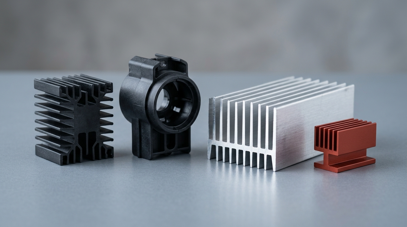
Thermally conductive plastic vs aluminum looks like a mismatch on paper: 0.7–5.0 W/m·K against 150–237 W/m·K. It is not a mismatch. It is a different thermal architecture, and the comparison only means anything once you know which resistance is setting your junction temperature.
In most low- to mid-power parts in still air, the largest term in the stack is convection off the surface into the air — not conduction through the plastic wall. That is why aluminum's headline number buys far less than the datasheet implies, and why a molded part can hold comparable surface temperature while cutting part weight by more than 30% and removing most of the assembly.
The judgment itself is one comparison. Work out the convective resistance at the surface, work out the conduction resistance through the wall, and see which one dominates. When convection dominates, the material on the inside barely moves the total and plastic wins on weight, part count, isolation and design freedom. When conduction dominates — concentrated heat, high power density, no airflow left to add — aluminum keeps the part. Everything below is that arithmetic, the dimensions it decides, and the honest list of cases where the answer is still aluminum.
Why the Conductivity Numbers Are Misleading
Every datasheet in this category leads with thermal conductivity in W/m·K, and the reflex comparison is against aluminum: 0.7–5.0 W/m·K for a filled engineering thermoplastic against 215–237 W/m·K for aluminum in the published tables of common materials and metals and alloys. The alloys this decision is actually about sit lower than that: the wrought grades used for extruded heatsinks run around 190 W/m·K, and standard die-cast grades are quoted near 150 W/m·K. Two orders of magnitude looks like a verdict. On most parts it is not.
Junction temperature is set by resistances in series, not by one number. Heat leaves the die, crosses the interface, spreads through the part, and finally leaves the outer surface into the air. Each stage has its own resistance, and they add. The material of the part only touches the middle stage.
Put numbers on it. A small finned part with 100 cm² of wetted surface in still air sees a convection coefficient around 5–10 W/m²·K, which puts the surface term at roughly 1/(10 × 0.01) ≈ 10 K/W. The wall over the same footprint, 3 mm thick at 2 W/m·K, contributes 0.003/(2 × 0.01) ≈ 0.15 K/W. Swap that wall to aluminum and it drops to 0.0015 K/W.
That is a hundredfold improvement on 1.5% of the problem. The total moved by a fraction of a kelvin per watt, and the part is still convection-limited.
| Term in the stack | Typical magnitude (100 cm² part) | What sets it |
|---|---|---|
| Conduction through the wall, 3 mm | 0.15 K/W plastic, 0.0015 K/W aluminum | Wall thickness and the material's λ |
| Convection off the outer surface | ~10 K/W in still air | Airflow (h) and surface area (A) |
Understanding what W/m·K actually measures — a bulk property under a defined test method — is the prerequisite for seeing why it cannot decide a whole assembly.
The same arithmetic explains the reverse failure. On a part with a concentrated 30 W load, a small footprint, and no room for more surface area, convection is no longer the bottleneck: the resistance inside the part and at the interface does dominate, and the material choice becomes decisive. The question is never "is plastic conductive enough." It is "which term owns this design."
Thermally Conductive Plastic vs Aluminum: The Numbers Side by Side
The comparison that matters is not one property but ten, and they do not all point the same way. This is the table the material suppliers' product pages do not publish — each of them competes on its own grade list rather than on a shared decision.
| Dimension | Aluminum (extrusion / die-cast) | Thermally conductive plastic | What it decides |
|---|---|---|---|
| Thermal conductivity (through-plane) | 215–237 W/m·K pure; ~190 W/m·K wrought, ~150 W/m·K die-cast; isotropic | 0.7–5.0 W/m·K; higher with graphite fill, lower with ceramic fill | Only decisive when bulk conduction dominates the stack |
| Density | ~2.7 g/cm³ | Specific gravity 1.45–1.8 | Weight saving of more than 30% on the same part volume — 33–46% across that SG band |
| Geometry | Constant cross-section on extrusions; draft and ejector constraints on castings | Injection molding: molded fins, pockets, hollow channels, snap-fits, bosses in one shot | The strongest argument for switching, and the least measurable on a datasheet |
| Part count | Fins, bracket, cover and fasteners are separate parts | One molded part can carry the thermal, structural and mounting functions | Removes assembly steps, not just material |
| Electrical isolation | Conductive; needs anodizing or an insulating interface to isolate | Volume resistivity ≥10¹² Ω·cm, dielectric strength 15–30 kV/mm — per grade | Simultaneous heat path and dielectric barrier, with no coating step |
| RF behavior | Reflects; shields the antenna inside a metal housing | RF-transparent, so an antenna can sit inside the enclosure | Decisive for 5G, Wi-Fi and IoT enclosures |
| Corrosion | Needs coating or alloy selection in wet or salt environments | Inherently corrosion- and oxidation-resistant | Lower lifetime risk in outdoor and marine-adjacent products |
| Continuous service temperature | 150 °C+ without difficulty | Grade-dependent: PP under 100 °C, PA/PBT 100–150 °C, PPS 200 °C+ | The hard ceiling that rules plastic out of some designs |
| Tooling economics | Machining is cheap at low volume and linear in quantity | Mold is a fixed upfront cost that amortizes with volume | Flips the decision at low annual volumes |
| Recyclability | High scrap value; energy-intensive primary production | Thermoplastic, remeltable, mono-material with the rest of the housing | A secondary factor, rarely the deciding one |
Two rows deserve emphasis. Design freedom is where the case is usually already decided before anyone runs the thermal numbers: a molded part can carry fins on a curved surface, put a threaded insert where the cable enters, and clip to the board with no separate bracket. And the recyclability row is real but modest — recycled-content grades exist, and a thermoplastic part can go back into the same material stream as the rest of the housing, but nobody should choose a material for this reason alone.
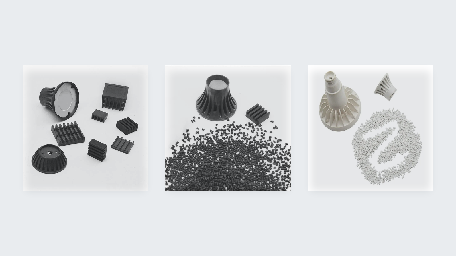
What thermally conductive plastic actually looks like as a finished part: molded finned heatsinks, a lamp housing, and the pellet feedstock the grades arrive as.
The current thermally conductive plastic grade list shows the shape of the real catalog: 13 part numbers across three resin backbones, spanning 0.7–5.0 W/m·K and specific gravities from 1.45 to 1.8. Note how wide that band is. Choosing "thermally conductive plastic" is not choosing a material — it is choosing a spot on a temperature-versus-conductivity trade curve, which the next sections make explicit.
When Plastic Wins: The Convection-Limited Rule
The decision rule is short enough to write down and reuse:
Compare the convective resistance at the part surface — Rth = 1 / (h·A) — with the conduction resistance through the wall, t / (λ·A). Whichever term dominates the sum is what your material choice has to move.
The two variables that actually decide the outcome are h, which airflow sets, and A, which the geometry sets. Neither is a material property. That is the whole reason a 5 W/m·K compound can serve a part that a 150 W/m·K alloy "should" win.
Read it in the two directions engineers hit in practice.
| Dissipated power, natural convection | Which term dominates | Practical route |
|---|---|---|
| Under ~10 W | Surface convection, Rth = 1/(h·A) | Molded thermally conductive plastic usually lands at comparable surface temperature |
| ~10–50 W | Both — geometry and airflow decide | Run the arithmetic before tooling; plastic can work with more area, forced airflow or a metal spreader |
| Above ~50 W | Bulk conduction and interface resistance | Aluminum, unless airflow or surface area changes by a large factor |
Under roughly 10 W in natural convection, the surface term dominates by an order of magnitude, and moving from aluminum to a mid-conductivity grade usually lands at comparable surface temperature with a larger, better-shaped finned area. This is the band where LED lamp housings, sensor enclosures, small power supplies and board-level brackets migrate most easily, and where the weight and part-count gains come for free.
Above roughly 50 W, conduction and interface resistances take over. Plastic can still work, but only if you change another variable: add forced airflow to lift h by a factor of five to ten, or significantly enlarge A, or spread the load across a metal spreader. Without one of those, aluminum keeps the part. Between 10 and 50 W, the answer depends entirely on geometry and airflow — and that is exactly the range where the arithmetic is worth doing instead of guessing.
Keeping the two resistances in the same units matters here, and the distinction between thermal resistance and thermal impedance is where datasheet comparisons quietly go wrong: an impedance quoted at a defined pressure and bond line is a system measurement, while W/m·K is a bulk property, and mixing them overstates one option and understates the other.
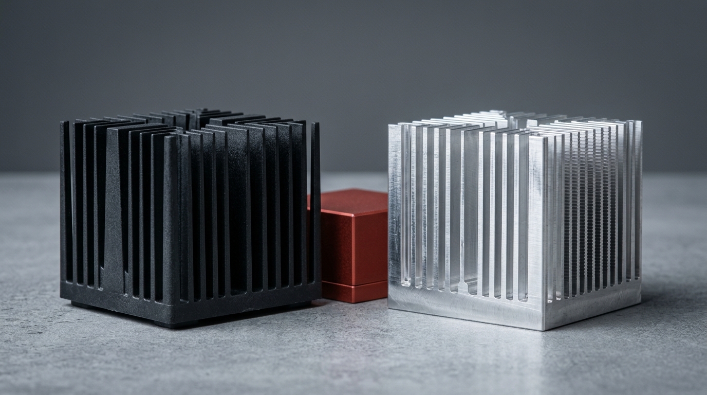
Same footprint, two routes to the same surface area. Once convection off the surface dominates, the difference between these two parts is weight, part count and isolation — not W/m·K.
If the enclosure around that part also has to hold potting or a foam gasket, the rest of the material stack is covered in the potting, encapsulation and thermal insulation for power electronics cluster — worth reading before the housing design freezes, because those choices change the effective surface area too.
Part Consolidation Is Usually the Bigger Win
Engineers ask whether plastic can replace aluminum. The more productive question is whether injection molding can replace machining plus assembly, because that is where the economics usually land.
An extruded aluminum heatsink is a constant cross-section by definition — the die sets the profile, and any feature that is not a slot running the full length becomes a second operation. A die-cast part escapes the cross-section limit but adds draft angles, ejector-pin constraints, porosity risk and a trimming step. Both routes end with a bracket, a cover and fasteners as separate items with their own part numbers, tolerances and inspection.
A molded compound is a net-shape process. The same shot can produce cooling fins on a curved surface, a snap-fit that replaces two screws, a boss with a molded-in threaded insert at the cable gland, a connector cut-out with the correct clearance, and reinforcing ribs that stiffen a wall you would otherwise thicken. The list of parts that disappear is often longer than the part that replaces them, and every removed fastener also removes an assembly step, a torque spec, and a failure mode.
There is a real cost on the other side of this trade, and it belongs in the same paragraph rather than a footnote. A mold is a fixed, upfront cost, and it only amortizes over the program volume. At low annual quantities, machining an aluminum part can be the cheaper route for years — which is why the material decision cannot be made without the volume forecast. The same logic explains why a design that ships in three variants may need three tool sets or one clever family tool.
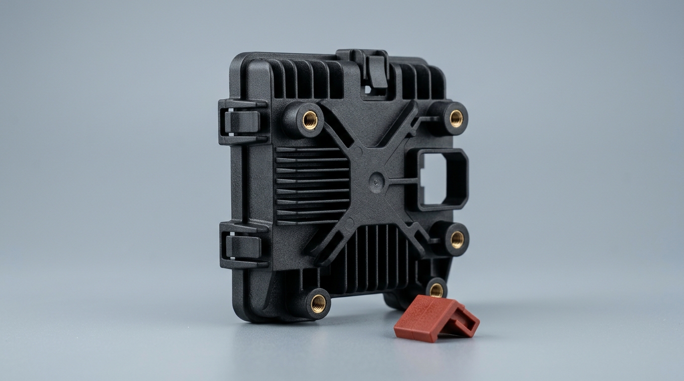
One shot, one part number: molded fins, snap-fit clips, threaded inserts and a connector cut-out that would be four or five items in an aluminum assembly.
Isolation and RF Transparency: Two Jobs Aluminum Cannot Do
The strongest arguments for a molded thermally conductive part are not about replacing aluminum's thermal performance. They are about jobs aluminum cannot do at all.
Electrical isolation in the same material as the heat path. A metal enclosure that must also isolate live parts needs a second material in the stack — anodizing, a coated insulator, or a separate barrier — and each of those adds a process step, a thickness tolerance and an inspection point. A filled polymer is a dielectric by nature: ceramic-filled grades are quoted at volume resistivity of 10¹² Ω·cm and above, with dielectric strength in the 15–30 kV/mm range depending on grade and wall thickness, measured under the methods in ASTM D257. One material then does both jobs, and the isolation cannot be scratched off in handling. Above about 1 kV continuous, read the per-grade datasheet rather than the family range, because thin walls derate.
Radio transparency. This is the one that decides whole product categories. A metal housing shields whatever antenna is inside it; a molded polymer housing does not, so the antenna can sit inside the enclosure without a plastic window, an external whip, or a lost-radio compromise. For 5G customer-premises equipment, Wi-Fi routers, IoT sensors and anything with a radio and a heat load in the same box, RF-transparent thermal plastic is not a cheaper aluminum — it is the enabler that lets the two functions share one wall.
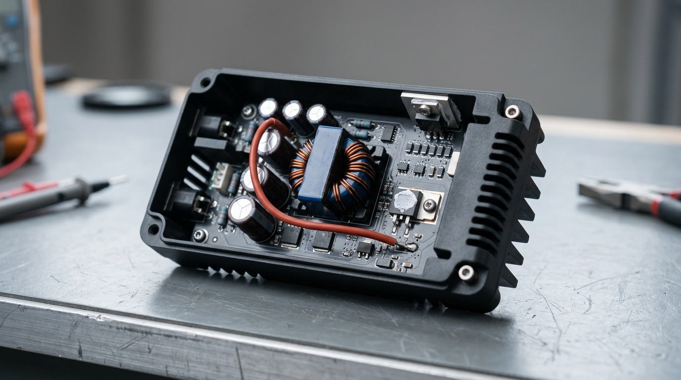
The enclosure is the heatsink. A molded housing like this dissipates heat, isolates live parts and passes RF in one part — three jobs a metal box splits across three materials.
At device level, the same isolation job is done by thinner, dedicated materials — the thermally conductive electrical insulators used between a package and a heatsink. The difference is scale: an insulator pad isolates one component, while a molded housing isolates the whole assembly and structures it at the same time.
Where Aluminum Still Wins
A comparison that only argues one direction is not worth reading, so here is the list of conditions where aluminum keeps the part. Any one of them can overturn the conclusion above.
Concentrated heat or high power density. Above roughly 50 W in natural convection, the surface term stops dominating and the two-order-of-magnitude gap starts to matter. Very small heat sources with high flux — a power device under 1 cm², a hot transformer core — are worse, because spreading that flux out is itself a job aluminum does well and a filled polymer does not.
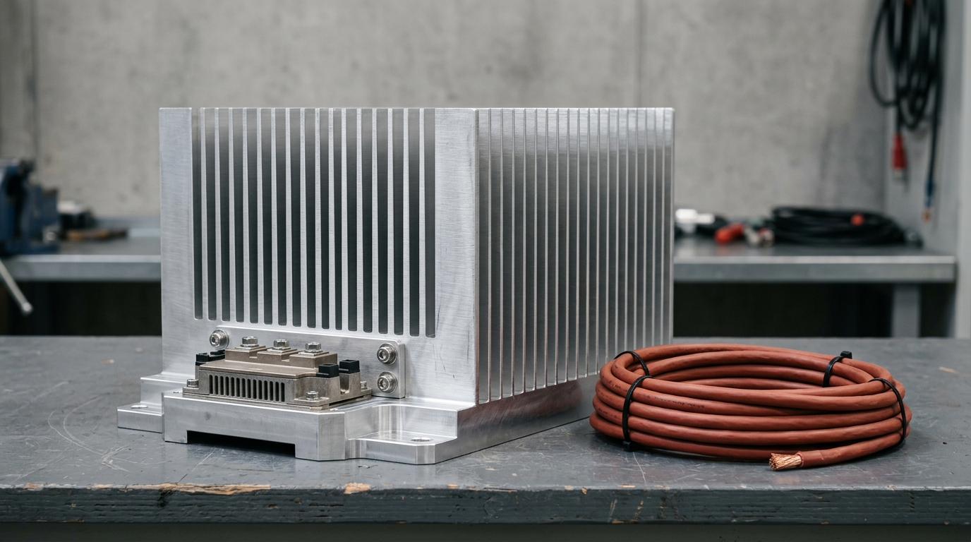
The case that keeps aluminum: a bolted power module on a heavy extruded heatsink. Concentrated flux, a small footprint and no spare airflow put the conduction term back in charge.
Service temperature that forces you into PPS. The resin backbone sets a hard ceiling, and above 200 °C it leaves only one family. PPS survives where PA and PP fail, but it does so at the lowest conductivity in the catalog — around 0.9 W/m·K against 5.0 W/m·K at the top of the PA/PBT range. The grade that survives the temperature is not the grade that wins the thermal argument, and that tension is real rather than rhetorical.
Stiffness, creep and dimensional stability. A molded part under a sustained clamp load at temperature will creep; a metal one will not. Thin, long, unsupported spans and precision interfaces are where this shows up, and where the honest answer is that the design needs aluminum or a hybrid.
Severe thermal cycling combined with vibration. Where a part sees large ΔT swings and mechanical excitation with no compliant interface, the differential expansion and the fatigue behavior both have to be designed for. Molded-in stress, knit lines and weld-line weakness are all additional variables that aluminum simply does not have.
Low annual volume. As in the previous section: below the mold's break-even quantity, machining wins on cash, whatever the physics says.
Maximum conductivity and electrical isolation at the same time. Graphite-filled grades reach the highest conductivities, but they conduct current as well as heat, so a design that needs isolation must step back to ceramic or boron-nitride fill and a lower W/m·K. Where the part needs both, the option set narrows sharply — and aluminum, with a separate insulator in the stack, is the simpler route.
Real programs frequently land in the middle. An EV battery pack, for example, usually ends up hybrid rather than single-material — metal where flux is high, polymer where the part is structural and isolating — and a worked example of that split is in the EV battery pack thermal management case. Aluminum's physical properties, including a thermal conductivity of 237 W/m·K in its pure form — lower once it is alloyed for an extrusion or a die-cast housing — are not in question. What is in question is whether your part needs them.
Choosing a Grade: PP, PA/PBT or PPS — and What the Datasheet Must Show
Once the decision rule says plastic, the next decision is which resin backbone, and the answer is driven by temperature before conductivity. The catalog splits three ways, and the conductivity ordering runs opposite to the temperature ordering — which is the clearest proof that W/m·K is not the selection criterion.
PP backbone, under 100 °C. Cost-tuned consumer parts: LED lamp housings, low-power adapters, covers. Lowest cost, lowest temperature class, and the hardest family to bring to a V-0 flame rating without heavy flame-retardant loading — if the program needs a UL Yellow Card, check that specific grade early.
PA / PBT backbone, 100–150 °C. Industrial and automotive parts, and the family that carries the top of the conductivity range — the highest-λ grade in the catalog reaches 5.0 W/m·K here.
PPS backbone, 200 °C and above. Fuel, oil and chemical exposure, high-temperature service. Conductivity drops to roughly 0.9 W/m·K, so the part needs more surface area for the same duty. PPS earns its place on chemical and thermal resistance, not on heat transfer.
| Resin backbone | Continuous service temperature | Thermal conductivity | Typical fit |
|---|---|---|---|
| PP | Below 100 °C | Bottom of the range | Cost-tuned LED housings, covers, low-power adapters |
| PA / PBT | 100–150 °C | Up to 5.0 W/m·K — the top of the catalog | Industrial and automotive parts, power electronics housings |
| PPS | 200 °C and above | Around 0.9 W/m·K — lowest of the three | Fuel, oil and chemical exposure, high-temperature enclosures |
The conductivity ordering running opposite to the temperature ordering is the practical proof that W/m·K is not the selection criterion. Pick the resin class on temperature and chemistry first, then take the highest conductivity available inside that class.
The filler system is the second decision, and it is electrical before it is thermal. Ceramic and boron-nitride fillers give a dielectric part — boron nitride is a common choice because it conducts heat without conducting current. Graphite fillers give the highest conductivity and a conductive part.
There is a ceiling on how far any filler takes you. Loading a polymer with conductive particles raises conductivity steeply at first and then flattens, because the particles have to connect before they can carry heat — the mechanism is set out in this review of filled-plastic thermal conductivity. That is why the range tops out in the single digits instead of approaching aluminum, and why a conduction-limited design usually needs a geometry change rather than a better compound. Graphite flakes also align with the melt flow, which makes conductivity direction-dependent: in-plane values can be several times through-plane values in the same part. If your thermal path runs through the wall thickness, quote through-plane numbers and check the test method — the per-grade datasheet is where that is stated, measured under a flash-method test such as ASTM E1461.
Molding follows standard practice, with three numbers worth carrying into the tooling discussion. Barrel temperatures run about 200–230 °C for PP grades, 270–290 °C for PA, and 320–340 °C for PPS. Mold shrinkage sits in the 0.3–0.7% band, comparable to other filled engineering plastics. Metal-oxide fillers are abrasive, so high-volume tools want mold steel at HRC 50 or harder. None of this requires special equipment — these compounds run on standard injection presses — but the tool does have to be specified for the filler.
Flame ratings are where teams get caught late. The higher-temperature grades are typically brought to UL 94 V-0 at 1.5 mm and thicker, and the low-temperature PP family is the harder case. Two caveats matter more than the headline rating: confirm it on the per-grade datasheet rather than the family page, and expect to re-test the part as molded at its actual wall thickness for a final-product UL listing. The distinction between the ratings themselves is covered in UL 94 V-0 vs VTM-0.
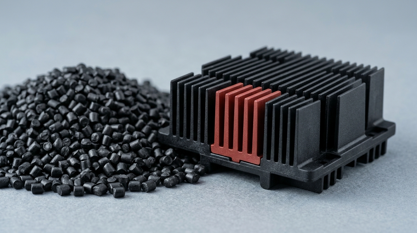
A grade is a pellet, not a part. The conductivity, filler and flame rating all belong to the compound; the wall thickness and flow path that decide the finished performance belong to your tool.
The Qualification Path and a Buyer's Checklist
Four steps take a molded thermally conductive part from CAD to production, and skipping any of them is how the thermal argument gets lost in validation.
1. Run the numbers on your geometry, not the family range. A short FEA with your actual CAD, plus a mold-flow pass to see how the filler orients through the part, tells you the real through-plane conductivity in the thick and thin regions. The datasheet gives a range; the simulation gives an answer.
2. Build and measure a sample. Measure junction temperature and interface impedance under production clamp torque and production fasteners, at the worst-case ambient. This is the only number that belongs to you.
3. Test the duty cycle. Thermal cycling and vibration per the program's requirements, with the molded part in its real stack-up. Watch for creep at clamp loads and for any change in flatness after cycling.
4. Close the compliance path. UL listing at the part as molded, RoHS and REACH declarations, and — for automotive programs — an IATF 16949 certified supply chain. Ask for the certificate stack with the datasheet, not after the design freeze.
Checklist to run before requesting samples, and again before approving production:
- Is the part convection-limited? Convective Rth computed and larger than the wall's conduction resistance.
- Dissipated power under 10 W in natural convection, or airflow/area available to exceed 50 W.
- Continuous service temperature inside the chosen resin class with margin, not at its edge.
- Filler system matches the electrical requirement — dielectric or conductive, chosen deliberately.
- Through-plane conductivity quoted, with its test method and thickness.
- Flame rating confirmed per grade, with the part-as-molded test planned.
- Volume vs mold break-even checked against the annual quantity forecast.
- Creep and cycling assessed for the clamp load and ΔT the part will actually see.
That is the method: one comparison of resistances, one geometry simulation, one measured sample, one compliance path. If the numbers land, the how to choose a thermal interface material guide covers the rest of the interface problem — the pad, gap filler or paste between the device and whichever material you choose.
If the part sits in that 10–50 W band where the answer is genuinely close, send the geometry and the power budget to ZIITEK's engineering team and have the convection-limited calculation run before the tooling decision is made. It is considerably cheaper than finding out after the mold is cut.