Silicone Foam for Vibration Damping & Cushioning
Silicone foam damps vibration only when compression set, cushion curve and loaded area match the mass. Compare it with PU, PORON and EPDM, then specify it.
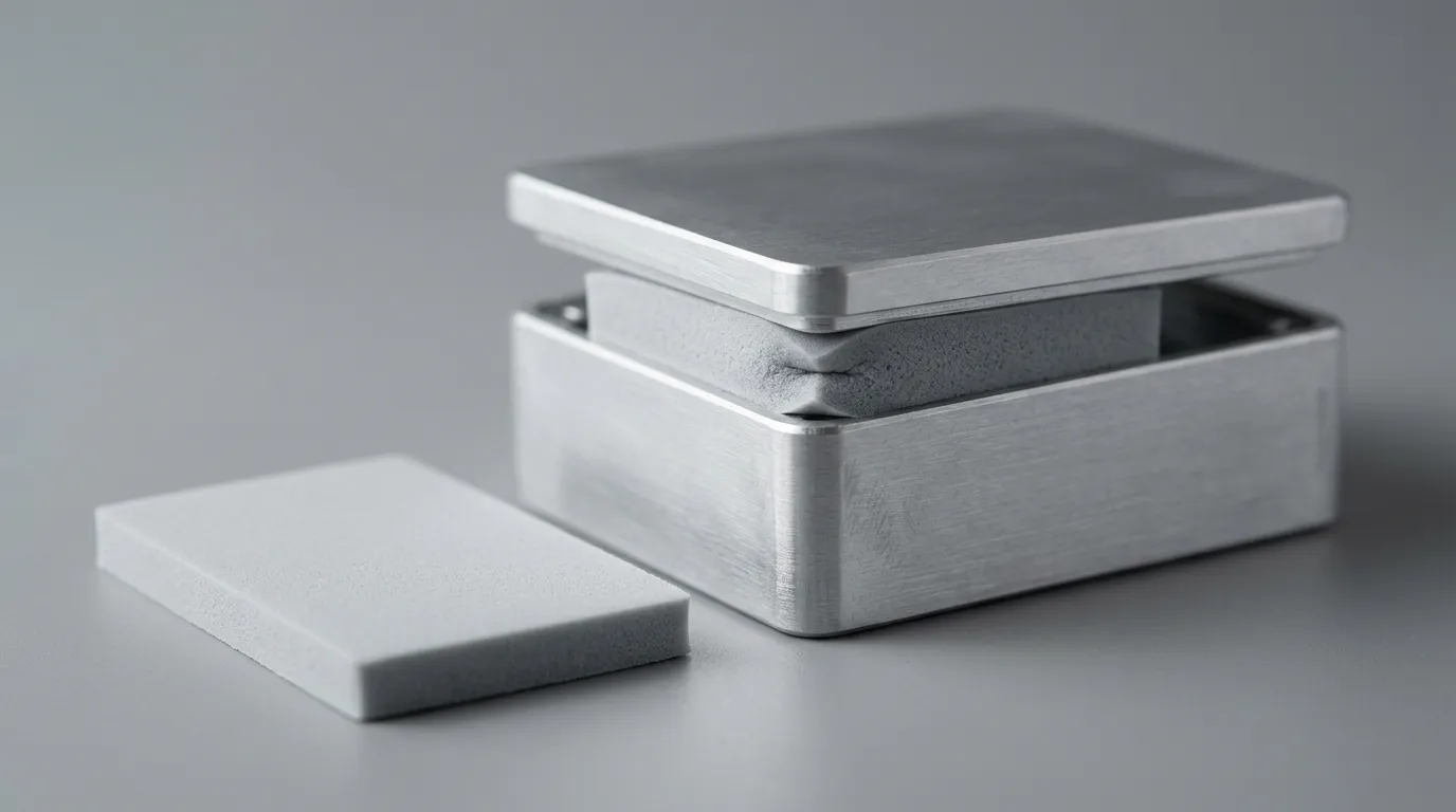
Silicone foam for vibration damping is bought as a cushion and specified as a cure for a vibration problem, and those are two different jobs. A pad that feels soft and springy in the hand can raise the acceleration a circuit board sees at 200 Hz, because softness by itself damps nothing: it sets the natural frequency of whatever mass sits on it, and the relationship between that frequency and the excitation decides whether motion is attenuated or amplified.
The mechanics behind that relationship are what this article is about, together with the numbers a drawing has to carry: compression set, compression force deflection, loaded area, thickness and the temperature the assembly will really see. It sits under the wider guide to silicone foam sealing and cushioning materials; here the subject is what happens to a foam pad under load and motion.
Damping, Isolation and Cushioning Are Three Different Jobs
Meetings use the three words interchangeably, then someone specifies a material and the three turn out to want different things.
Isolation is a transmission problem. A mass on a spring has a natural frequency; excitation below it passes through almost unchanged, excitation near it is amplified, and only above roughly 1.4 times the natural frequency does the mount begin to reduce what reaches the mass. That ratio of what arrives at the mass to what enters the mount is the transmissibility: about 1.0 at the crossover, greater than 1 below it, and falling steadily past it. Isolation is bought with compliance and mass, not with a product label that says damping.
Damping is an energy problem. The damping ratio describes how quickly a material converts motion into heat, and its most visible effect is at resonance: peak amplification falls roughly as the inverse of twice the ratio, so a well-damped mount tops out lower than a springy one. Above the isolation region the same damping slightly reduces the benefit, which is the classic trade-off in mount design.
Cushioning is a stroke problem. In a drop or an impact the pad has a limited distance in which to stop a mass, and the question is whether peak deceleration stays inside what the contents tolerate. Energy has to go somewhere — into cell collapse, into hysteresis, into the pad's own deformation — and a material that stores it and gives it back is a spring, not a cushion.
A foam gasket inside an enclosure is asked to do all three at once, and usually does at least one of them badly. That is why a cushioning specification consisting of a thickness and a hardness number is not a specification; it is a guess with units attached.
A soft pad does not absorb vibration. It moves the problem to whatever frequency the mass on top of it happens to resonate at.
What a Foam Has to Deliver Under a Compressive Load
Compression set decides whether the pad is still there in year three
Compression set is the strain a material keeps after the load is removed, expressed as a percentage of the deflection it was given. ASTM D395, the standard test method, defines two methods; Method B — constant deflection — is the default. Foam specimens are normally compressed 50% for 22 h at 70 °C, or at 100 °C where the service temperature is higher, and then allowed to recover. The calculation compares thickness lost with deflection applied:
set = (original thickness − recovered thickness) / (original thickness − spacer thickness) × 100
A pad with 5% set has given back 95% of the distance it was squashed; a pad with 40% set has turned two-fifths of its working stroke into permanent flatness. For a seal that means lost contact pressure. For a cushion it means the next impact starts part-way through the stroke, and the acceleration peak climbs.
Compression set and stress relaxation are frequently conflated. Set is retained strain once the load is gone; relaxation is lost push-back while the strain is held. Silicone is unusually good at both, and Stockwell Elastomerics' test notes set out the measurement and the distinction in plain terms.
Compression force deflection is the stiffness you actually get
Hardness on a foam datasheet is a poor predictor of load-bearing behavior — a durometer reading says little about the force a pad develops. The useful number is compression force deflection — the stress needed to compress the pad by 25% — which ASTM D1056 treats as a graded property of sponge and expanded rubber, alongside density, compression-deflection and water absorption tests. That specification is what most foam gaskets are bought against, and its grades exist precisely because "soft" covers a wide span of load-bearing behavior.
CFD scales with loaded area. A pad of the same material and thickness specified over twice the area takes twice the force for the same deflection, so a change of footprint is a change of spring rate even when nothing else moves.
Thickness sets the stroke and the strain
Stiffness of a pad in compression varies roughly with area over thickness, and strain is deflection divided by free thickness. Halving the thickness at the same deflection doubles the strain and pushes the material up its stress-strain curve, where it stiffens quickly. That is the mechanism behind the most common cushioning failure: a pad that performed on the bench was thinned to suit a revised stack-up and now bottoms out.
The cushion curve is the only honest summary
For impact work the material property that matters is not a single modulus but a family of curves: peak deceleration against static loading, for a given drop height and thickness. MIL-HDBK-304B, the US military handbook on package cushioning design, remains the clearest public statement of the method, foam curves included. Read one and the shape is obvious: too little load and the pad is too stiff for the mass, too much load and it bottoms out, and between the two there is a minimum. A foam chosen without that curve is chosen on feel.
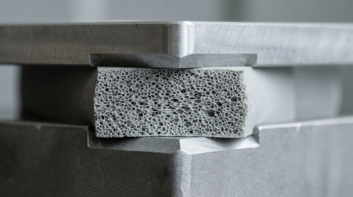
Illustration of a foam pad at working deflection — not a photograph of a specific product.
Why a Low Modulus Is Not the Same as Good Damping
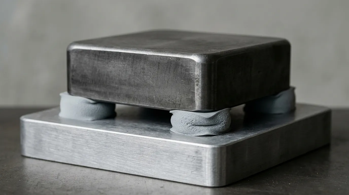
Illustration of a mass-on-foam-pad arrangement — not a photograph of a specific product.
Press a mass onto a foam pad and the relation looks forgiving: softer foam means more static deflection, a lower natural frequency and, in principle, better isolation. For a simple spring the two are locked together, with natural frequency falling as the inverse square root of static deflection — about 15.8 Hz for a millimeter of sag, 5 Hz for ten. Nothing about that relation rewards softness beyond what the geometry can afford.
Three limits cut in.
The first is stroke. Every millimeter of static sag is a millimeter of travel the pad no longer has for motion, so a very soft pad in a thin enclosure is a pad that bottoms out on the first hard shock and then transmits everything.
The second is that foam is not a linear spring. Silicone foam stiffens as its cells close, so effective natural frequency rises with amplitude; a pad tuned for small vibration behaves like a harder pad in a real event.
The third is that damping ratio, not modulus, sets the peak. Silicone foam's viscoelastic character gives it useful hysteresis, but the ratio is modest, and a pad that resonates with a fan or a motor harmonic will amplify that harmonic no matter how soft it is. In transmissibility terms that peak sits at roughly 1/(2ζ) — near ten times the input, about +20 dB, at a damping ratio of 0.05, and near three times at 0.20. Moving the natural frequency away from the excitation is the fix; damping only lowers the peak passed through on the way.
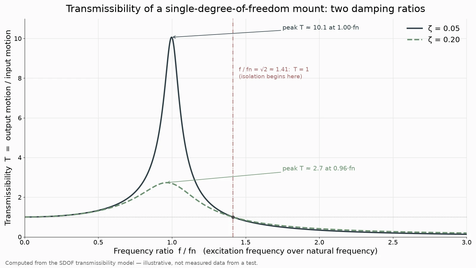
Computed illustration of the single-degree-of-freedom transmissibility model at ζ = 0.05 and 0.20 — a model output, not measured data from a test.
Silicone Foam Against PU, PORON, EPDM and Gasket-Style Seals
The comparison that matters is not silicone against "foam" in general but silicone against the specific material an engineer would otherwise put in the same cavity.
| Material | Rebound and set | Temperature | Where it fits | Where it fails |
|---|---|---|---|---|
| Silicone foam, closed cell | Low set, good rebound after long compression | Wide, roughly −55 °C to 200 °C | Sealing plus cushioning, outdoor and high-temperature enclosures | Higher cost than PU or EPDM sponge |
| Silicone foam, open cell | Fast rebound, softer | Wide | Light cushioning, dust sealing at low force | Water passes unless compressed |
| Microcellular PU (PORON type) | Very good set resistance at moderate temperature | Narrower | Thin, precise cushions in consumer devices | Properties fall away as temperature climbs |
| EPDM or CR sponge | Adequate cold, degrades hot | Moderate | Weather seals where cost dominates | Compression set rises sharply with heat |
| Solid silicone gasket | Excellent set resistance | Wide | Sealing where deflection is small | Too stiff to cushion; transmits shock |
The open-cell versus closed-cell question inside the silicone family is a separate decision, covered in open-cell vs closed-cell foam for gaskets; the short version is that closed cells seal and open cells breathe, and only one of them can be relied on to keep water out.
Against solid elastomers the trade is equally blunt: a solid silicone gasket seals beautifully and cushions badly, which is why rubber versus silicone gaskets comes down to deflection, not material prestige.
Stockwell's silicone foam material notes are a useful check on the claims made for the family: low compression set, a wide service window, flame ratings, and the reminder that water resistance depends on cell structure and density rather than on silicone alone.
Temperature and Time: Where Cushioning Quietly Fails
Compression set is measured hot for a reason. Heat accelerates the processes that steal rebound, and the datasheet figure is produced under conditions deliberately harsher than most applications — good for ranking materials, unreliable for predicting one assembly. Time at temperature is the variable that rarely appears on a drawing and always appears in the field.
It shows up as three patterns. A pad that met its set specification at room temperature creeps under a battery module that runs warm eight hours a day. A seal that passed a leak test on the line relaxes enough over a year of thermal cycling to lose contact pressure. And a cushion that survived qualification takes a set after a few hundred cycles at the top of its range, so the stroke available in year five is shorter than the stroke that was tested.
Silicone's advantage is not that it ignores heat but that its useful range extends well past where hydrocarbon elastomers start to degrade. That matters in EV work, where a single part often has to hold battery pack sealing through thermal cycling, road vibration and occasional immersion, with the cushioning and sealing duties landing on the same piece of foam.
Specifying Silicone Foam for Vibration Damping
A workable cushioning specification has six lines, and each one closes a failure mode.
| Parameter | What goes on the drawing | Failure mode it prevents |
|---|---|---|
| Thickness and deflection | Free thickness from the required stroke; service deflection kept to a fraction of it | Bottoming out, permanent set |
| Density and CFD | Compression force deflection at 25%, with tolerance | Pad too stiff or too soft for the mass |
| Loaded area and pattern | Effective loaded area, continuous pad or discrete pads | Spring rate changing with footprint |
| Attachment | Adhesive type rated for shear, or mechanical retention | Pad migration under vibration |
| Temperature and aging | Maximum continuous temperature and cycle count | Creep and set in service |
| Sealing and flame | Ingress rating and flame rating where required | Water ingress, flammability non-compliance |
Two of those lines deserve more than a cell. On deflection: the compression-set test uses 50%, and a pad that lives near that figure has spent its travel before the first hard shock arrives. On attachment: pressure-sensitive adhesive is the usual answer and the usual failure point, because vibration loads the bond in shear, and a tape rated for peel is not necessarily rated for that.
One worked example, with its assumptions stated. A 1.0 kg module rides on four 10 × 10 mm pads of 6 mm free thickness, in a grade whose CFD at 25 % is 30 kPa — the lower half of the 20–110 kPa span ZIITEK quotes. Loaded area is 4 × 100 mm² = 400 mm² = 0.0004 m², so static stress is 9.81 N ÷ 0.0004 m² = 24.5 kPa, which puts the pad just under 25 % compression. Secant stiffness there is (30 kPa ÷ 0.25) × 0.0004 m² ÷ 0.006 m = 8000 N/m. Static deflection is 9.81 N ÷ 8000 N/m = 1.23 mm, and fn = (1/2π)√(8000 ÷ 1.0) = 14.2 Hz, which the 15.8/√δ shortcut confirms: 15.8 ÷ √1.23 = 14.2 Hz. A 200 Hz fan harmonic lands at 14 × fn, where T ≈ 1/|1 − 14²| ≈ 0.005, so it is isolated. A 15 Hz transport input is not: 15 ÷ 14.2 = 1.06, on the shoulder of the peak. Doubling the pad to 12 mm halves k to 4000 N/m, drops fn to 10 Hz and puts 15 Hz at 1.5 × fn, above the crossover. Illustrative arithmetic, not measured data.
When the cushion also has to keep water and dust out, the grade needs an ingress rating — IP68 is defined in the IEC's ingress protection ratings — and if the product is a battery pack or a mains-powered enclosure, a flame rating as well. ZIITEK's Z-FOAM®800 silicone foam gasket carries UL94-V0 and IP68 together, is specified for compression rebound and impact resistance as well as sealing, and lists a 25% compression stress range of 20–110 kPa, density of 0.20–0.42 g/cm³, a compression set of 3–5% and thermal conductivity around 0.06 W/mK, low enough that a sealing gasket does not become a thermal bridge. The same family is where UL94 V-0 silicone foam selection starts when a flame rating is the driving requirement rather than an extra.
Parts are produced by die-cutting and custom converting from foam stock that includes Z-FOAM®800 and 7000, NBR, PORON and CR foam. That matters for cushioning work, because the geometry of a die-cut pad — corner radii, ring width, the ratio of cut edge to loaded area — changes how it behaves under load almost as much as the material does.

Illustration of die-cut foam parts — not a photograph of a specific product.
Failure Modes That Surface After the First Field Return
Bottoming out. The pad compresses to solid, stiffness rises by an order of magnitude, and the protected mass takes the shock directly. Cause: too little thickness for the stroke, or a tolerance stack that closed the gap after the drawing was released.
Over-compression and cell collapse. Closed cells crushed past their elastic limit do not reopen. The pad looks intact and measures thinner.
Creep under static load. A pad held compressed at temperature keeps losing thickness. This is compression set in slow motion, and it is why a seal that passed on day one leaks in year two.
Adhesive shear. The pad stays flat and slides. Vibration loads the adhesive in shear, and a tape rated for peel is not necessarily rated for that.
The wrong durometer for the wrong reason. A soft foam chosen to "protect" a component can be too soft to stop it moving, while a firm foam chosen for stability transmits too much. The answer is usually a specific CFD at a specific loaded area, which is a design calculation rather than a catalog pick.
What to Test Before the Drawing Is Released
Three tests cover most of the risk, and none of them is exotic. Compression set at the maximum service temperature, on the actual thickness and cell structure rather than a catalog value. A static load test at the specified deflection, held long enough to see relaxation — days, not minutes. And a shock or vibration test on the real assembly, because boundary conditions such as fasteners, housing stiffness and adjacent components shift the natural frequency more than the foam choice does.
Cushioning is one of the few areas where a modest amount of measurement replaces a great deal of argument: the material is doing mechanical work, and every number that describes it can be measured.