How to Specify Die Cut Gaskets & Thermal Pads
Die cut gaskets seal, thermal pads conduct heat — same die, opposite rules. Here is the six-point RFQ spec, with real material data and how tolerance is set.
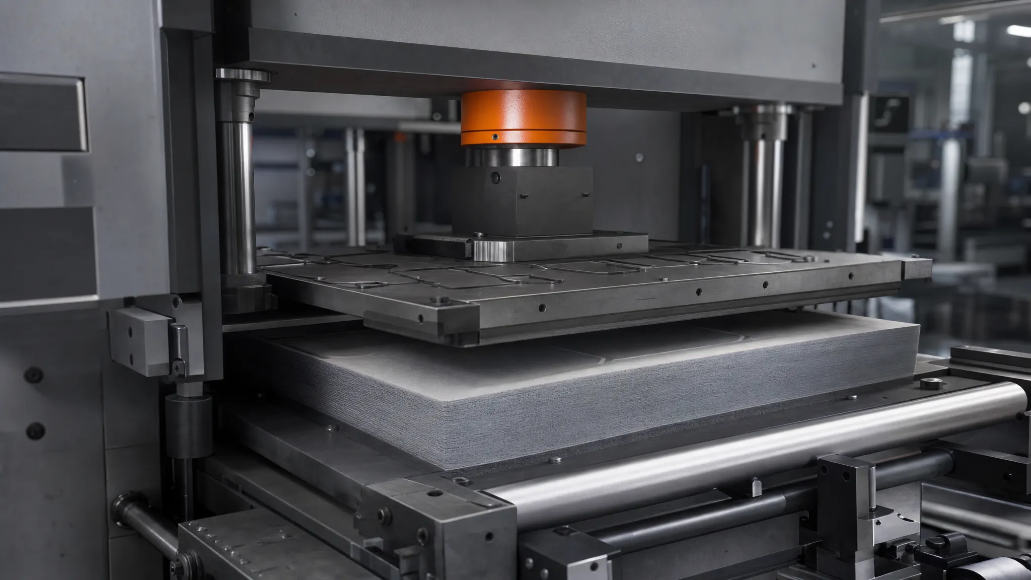
A drawing that reads "silicone gasket, 2 mm" and nothing else is how most die cut gaskets and thermal pads go wrong. The die cutter produces exactly what the drawing shows. The failure lands at first article: foam squeezed to 40% of its thickness that never recovers and quietly stops sealing, or a pad asked to cool a 12 W package while half its surface touches air because nobody defined how far it should compress.
Both parts come off the same press, from the same roll stock, under the same tooling economics — yet they are specified by rules that pull in opposite directions. What follows is what each part has to do in the stack, why die cutting gaskets and thermal pads is a profile process with limits of its own, and the six items that belong on a request for quote before anyone cuts a die.
Two Jobs, One Die: Sealing Gaskets vs. Thermal Pads
Start with function, not material. A sealing gasket blocks media — dust, water, air, a radiated field — and it does that by staying compressed against both mating surfaces for the life of the product. A thermal pad moves heat across a mechanical gap, and it does that by deflecting just enough to conform to both surfaces at the lowest force the assembly can apply.
That difference decides almost every number on the drawing.
| What the part must do | Sealing gasket | Thermal pad |
|---|---|---|
| Primary job | Block media ingress: dust, water, air | Conduct heat across a mechanical gap |
| How it works | Held in compression past its sealing threshold | Deflected until it conforms to both surfaces |
| Number that governs it | Compression stress at the target deflection, plus permanent compression set | Thermal impedance at the assembly's pressure and bond line thickness |
| How it fails | Takes a compression set, stops recovering, leaks | Under-compressed, leaving air gaps, or over-compressed, loading the package |
The conflict is predictable. A seal needs deep deflection, because foam has to push back against two surfaces that are never perfectly flat. A thermal pad usually needs shallow deflection: enough to close the air gap, not so much that it loads a package, a solder joint or a connector. Specify one like the other and the assembly will tell you.
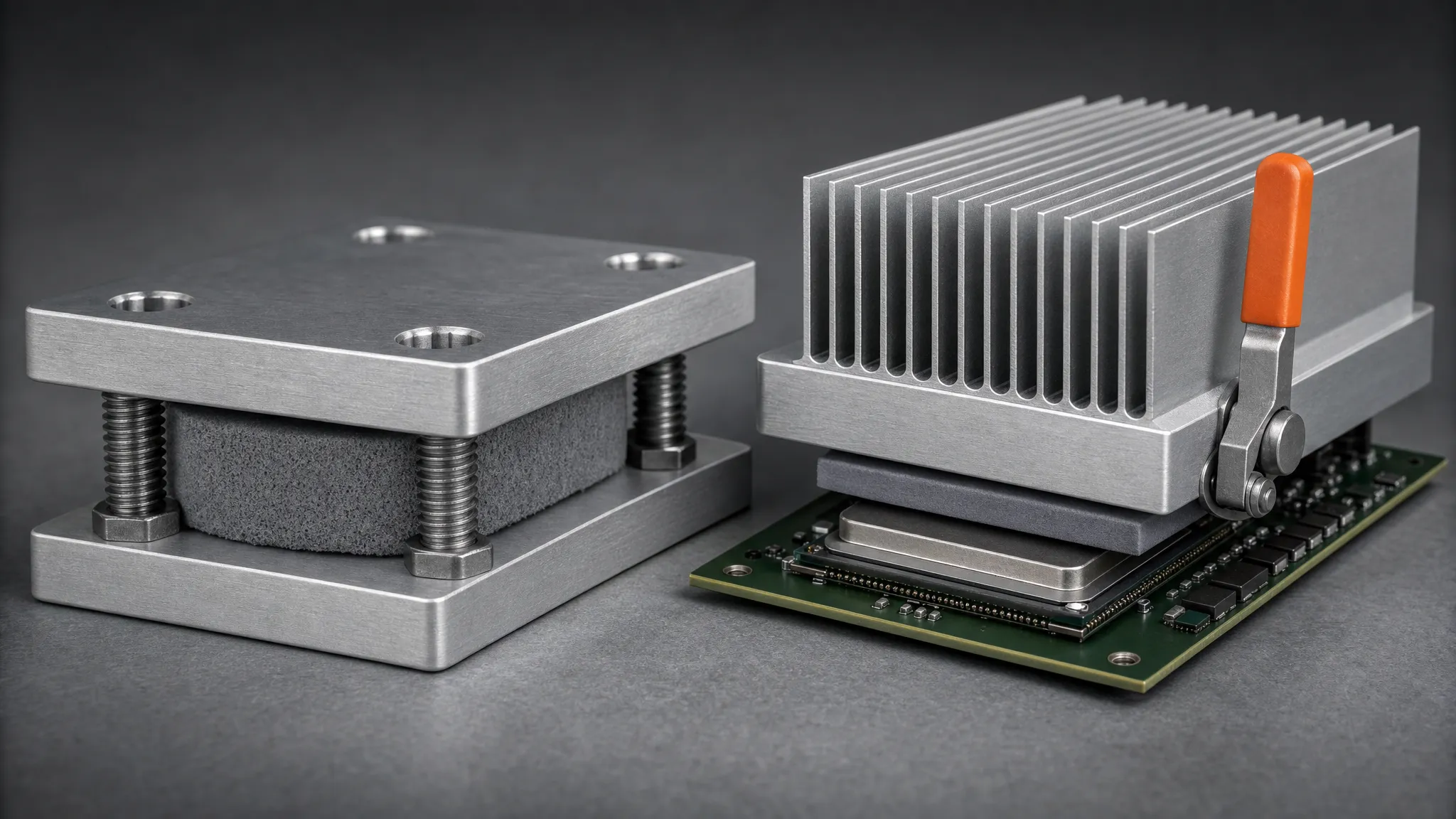
Same stack, same die, two different jobs: the seal is compressed deep enough to push back, the pad only far enough to close the gap.
Silicone is the usual starting point for both, because it holds its properties across roughly -45 °C to 200 °C and can carry a UL 94 V-0 flame rating. Most die cut silicone gaskets and pads share that base polymer; what differs is the filler. Die cut foam gaskets use an unfilled or lightly filled compound — Z-FOAM®800 silicone foam takes 20 to 110 kPa to compress 25%, holds a permanent compression set of 3-5% or better, and carries UL 94 V-0 together with IP68. Thermal grades are heavily filled with ceramic or carbon: the TIF® pad range covers 1.25 to 16 W/mK in thicknesses from 0.25 mm to 12 mm and hardnesses from 5 to 70 Shore OO, while the non-silicone Z-Paster®100 range covers 1.5 to 10 W/mK for assemblies where silicone outgassing is unacceptable. A third family covers parts that must also block current — die-cut thermal insulators for power devices hold up to 1,500 to 6,000 VAC breakdown.
If you are still working out which of these part families you need, what a thermal pad is and how it is specified covers the boundary against a dispensed gap filler — a distinction that changes the whole drawing, because a pad is cut to a fixed thickness and a gap filler is not.
Some parts have to do two jobs at once. Sealing and conducting in one part is achievable — a foam seal laminated to a thin thermally conductive layer, or an insulator with a pad bonded to one face, is cut as a single part in a single pass. It only works if the drawing describes both functions and both compression targets.
How Die Cutting Turns Sheet Stock Into a Part
Die cutting is a compression process: a shaped blade — a steel rule bent into the part outline and set into a laser-cut board, or a machined solid steel die for tighter tolerances and longer runs — is pressed into the material by a flatbed press for sheet stock. Rotary die cutting mounts the same blade on a cylinder and runs it against continuous roll stock, which is how high-volume programs cut. Both are profile processes: cost is set by the die and the nesting, not by how complicated the outline looks on a CNC router. Gasket die cutting, pad cutting and insulator cutting all run on the same equipment; what changes is the material and the tolerance the blade can hold.
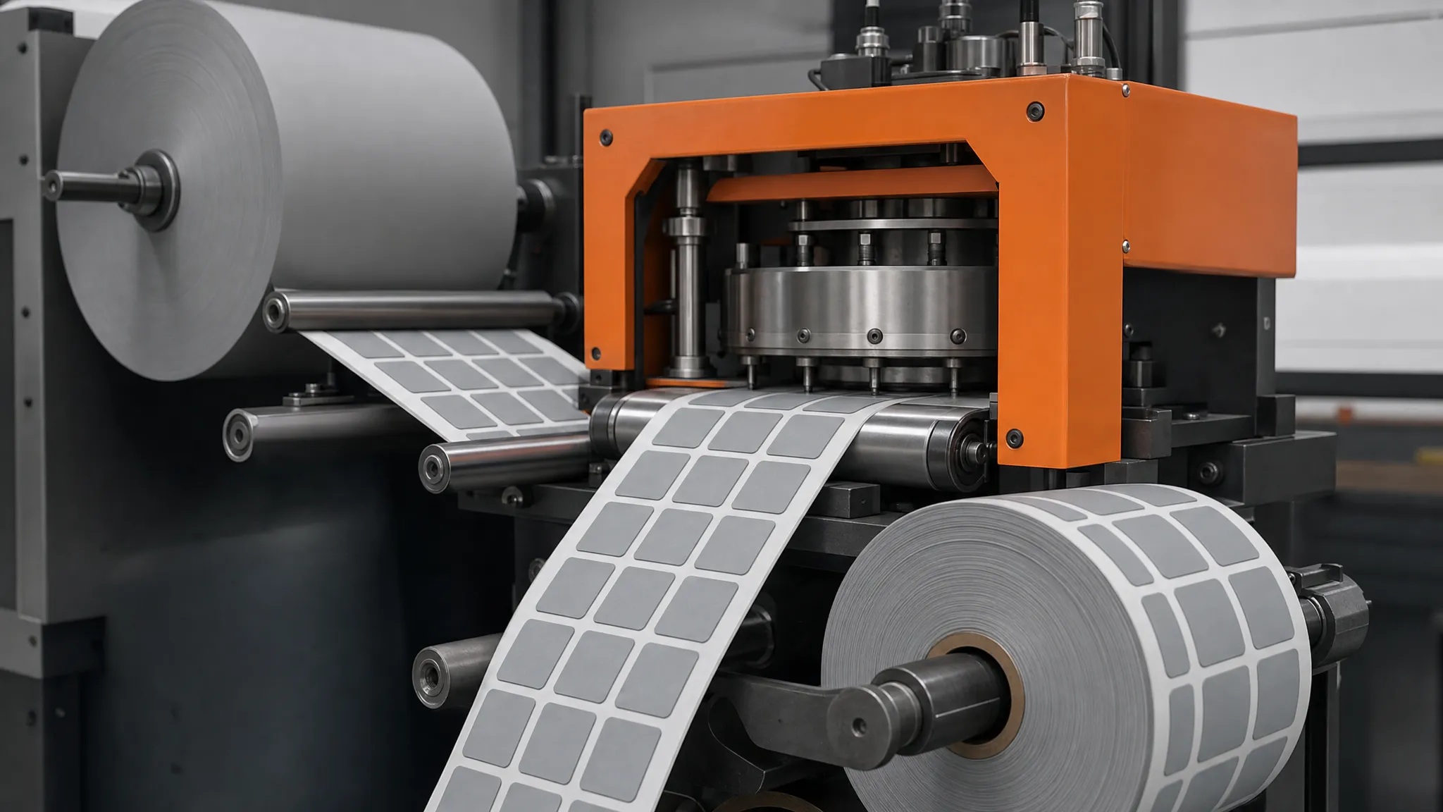
Roll stock in, die-cut parts out: the same line produces sealing gaskets and thermal pads, and the supply format is decided at this stage.
Three choices here decide what you can draw:
- Through cutting yields loose parts or sheets. Easy to inspect, more handling per part.
- Kiss cutting drives the blade through the material but only into — not through — the adhesive liner, so finished parts stay on a roll and feed straight into assembly. It is the default supply format for die cut thermal pads and gaskets that an operator peels and places, or that a dispenser feeds.
- Upstream lamination and slitting decide whether you cut one material or a stack: foam plus adhesive plus liner, or a pad plus a carrier film.
What die cutting cannot do is hold sheet-metal tolerances. Soft materials deflect under the blade, so dimensional tolerance scales with material thickness and part size, and it is quoted per feature rather than per part. The geometry limits below are working rules of thumb from shop experience, not published standards — every converter sets its own, so confirm the exact numbers with the shop that will cut your part:
- A hole smaller than the material thickness is usually treated as unreliable. The blade has to punch through the full stack, and small holes in thick stock distort. Where that limit actually sits depends on the grade and on the die, so ask the converter for the smallest reliable hole in the material you have chosen.
- Narrow flanges lose tolerance first. A wall narrower than the material thickness has nothing to support it and tends to come out with a concave edge. Minimum flange width is an experienced shop limit rather than a specification — it moves with material, thickness and die condition, so confirm it with the converter before you design to a dimension.
- Edges go slightly concave as thickness grows. The die squeezes material before it cuts it, and the effect worsens with stock thickness and density. How much is a shop answer, not a standard value: it is commonly acceptable on a seal and less acceptable on a visible trim part, so cut a first article in the real grade before committing the geometry.
- Nesting decides cost. Steel rule dies position parts to nest on the sheet, which is why die cutting usually wastes less material than waterjet or digital knife cutting on the same job.
When a design is still moving, tooling-free cutting on the same converting line covers prototypes and short runs — slitting, laminating and die-cutting and custom converting capability for thermal materials sit in one production cell, so a design change does not force a supplier change.
Specifying Die Cut Gaskets: What Actually Governs the Seal
Hardness is the spec most drawings give and the least useful one. A 30 Shore OO foam and a 50 Shore OO foam can seal the same enclosure, because what closes a gap is the force the gasket generates at the deflection your assembly produces — not the durometer on its own. Specify these five things instead:
- Compression stress at the working deflection. State the load required to compress the part to its installed height. Silicone foam sealing grades commonly sit in the band where 25% deflection takes roughly 20 to 110 kPa; picking a grade inside that band is how you match the seal to the force the enclosure can apply without distorting it.
- Permanent compression set. This is the number that explains leaks appearing three months after launch. A foam with 3-5% set returns to nearly its original thickness after cycling; a material that takes a set keeps the memory of being squeezed and lets the joint relax.
- A deflection window, with both bounds. Below the lower bound the seal never closes; above the upper bound the foam takes a set and stops pushing back.
- The ingress rating with its test condition. IEC 60529 defines IP68 as dust-tight plus protection against continuous immersion, with the immersion conditions agreed between manufacturer and user. An "IP68 gasket" is therefore not a specification on its own: the rating means something only when the depth, duration and compression are stated. Die-cut silicone foam gaskets that hold an IP68 seal are specified that way.
- Adhesive and liner, if the part has to stay put. A pressure-sensitive adhesive backing turns a loose gasket into a part an operator can place in one motion, which removes a fixture from the line.
A die cut gasket that passes first article and fails in the field has almost always failed on set or deflection, not on material choice.
Specifying a Thermal Pad: Thickness, Compression and Thermal Impedance
Die cut thermal pads arrive with a W/mK number on the datasheet, and that number is not the one that predicts junction temperature. Thermal impedance at the pressure and bond line thickness your assembly produces is — which is why ASTM D5470 measures steady-state thermal impedance under flat-plate conditions and derives apparent thermal conductivity by testing several thicknesses of the same material and plotting impedance against thickness. That flat-plate figure is the right basis for comparing grades, but the standard itself warns that the values it produces cannot be applied directly to most practical applications, where the required uniform, parallel heat conduction conditions do not exist. Your junction temperature has to come from impedance measured at your own pressure and bond line: a 6 W/mK pad compressed to the wrong thickness can easily perform worse than a 3 W/mK pad compressed correctly.
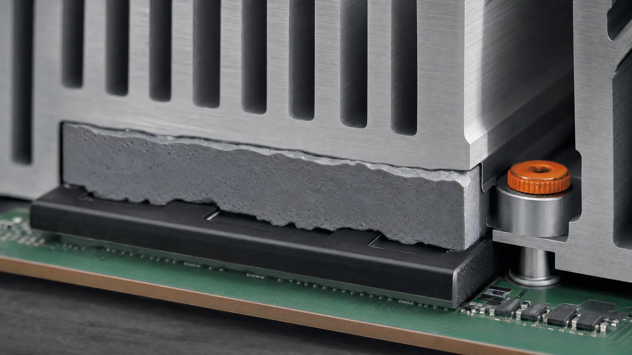
Compression is the design variable: too little and the pad only touches the high points, too much and it loads the package instead of the gap.
A pad specification has three parts:
- Nominal thickness, and how thickness is measured. Pad thickness sets how much deflection the assembly will produce. Soft materials are gauged at a defined pressure, so if the drawing does not say how thickness is verified, the supplier and incoming inspection will disagree about the same part.
- Intended compression, and the force that produces it. Under-compression leaves part of the gap filled with air; over-compression loads the package. Ask for the deflection curve of the candidate grade at your assembly force rather than assuming a percentage, because the curve for a soft 5 to 70 Shore OO spread varies sharply across the range. Thermal pad thickness and compression works through the gap-to-deflection relationship.
- The thermal value with its test condition. W/mK alone says little about a thin pad with high contact resistance; thermal impedance at a stated pressure and thickness is the comparable number.
Two secondary decisions matter almost as much:
- Hardness, expressed as Shore OO on soft pads, is your lever for low-pressure assemblies. The soft end conforms under light force; the hard end takes higher loads without collapsing into the gap.
- Silicone or non-silicone. Low-molecular-weight siloxanes can migrate and foul optical surfaces or open relay contacts, so assemblies with optics or exposed contacts need a non-silicone grade rather than a standard silicone pad.
Because thermal pad die cutting is a profile process, X-Y tolerance matters far less than thickness tolerance. The pad has to cover the die area, but a 0.2 mm shift in outline rarely causes a failure. Thickness error changes the pressure, and pressure changes the thermal result.
What Your Drawing and RFQ Need to Say
Most rework on custom die cut gaskets and die cut thermal interface materials traces back to an RFQ that left out one of six items.
| # | Item | What to write |
|---|---|---|
| 1 | Function | Seal, conduct, insulate or a named combination — plus the failure that must not happen |
| 2 | Material and compliance | Base material with filler, flame rating (UL 94), RoHS and REACH, IP target, and automotive quality system if it applies |
| 3 | Thickness and compression | Nominal thickness, thickness tolerance, installed height, and the force your assembly applies |
| 4 | Geometry rules | Hole and slot sizes relative to material thickness, minimum flange width, corner radii, adhesive and liner |
| 5 | Supply format | Through-cut loose parts, kiss-cut on liner, part-on-roll, or sheeted stock |
| 6 | Volume and prototypes | Prototype quantity and annual volume — this sets die class and per-piece price |
Item 5 is the one buyers most often leave out, and it moves assembly cost the most: a kiss-cut part on a liner that feeds a dispenser removes a manual step, while loose cut pieces add one.
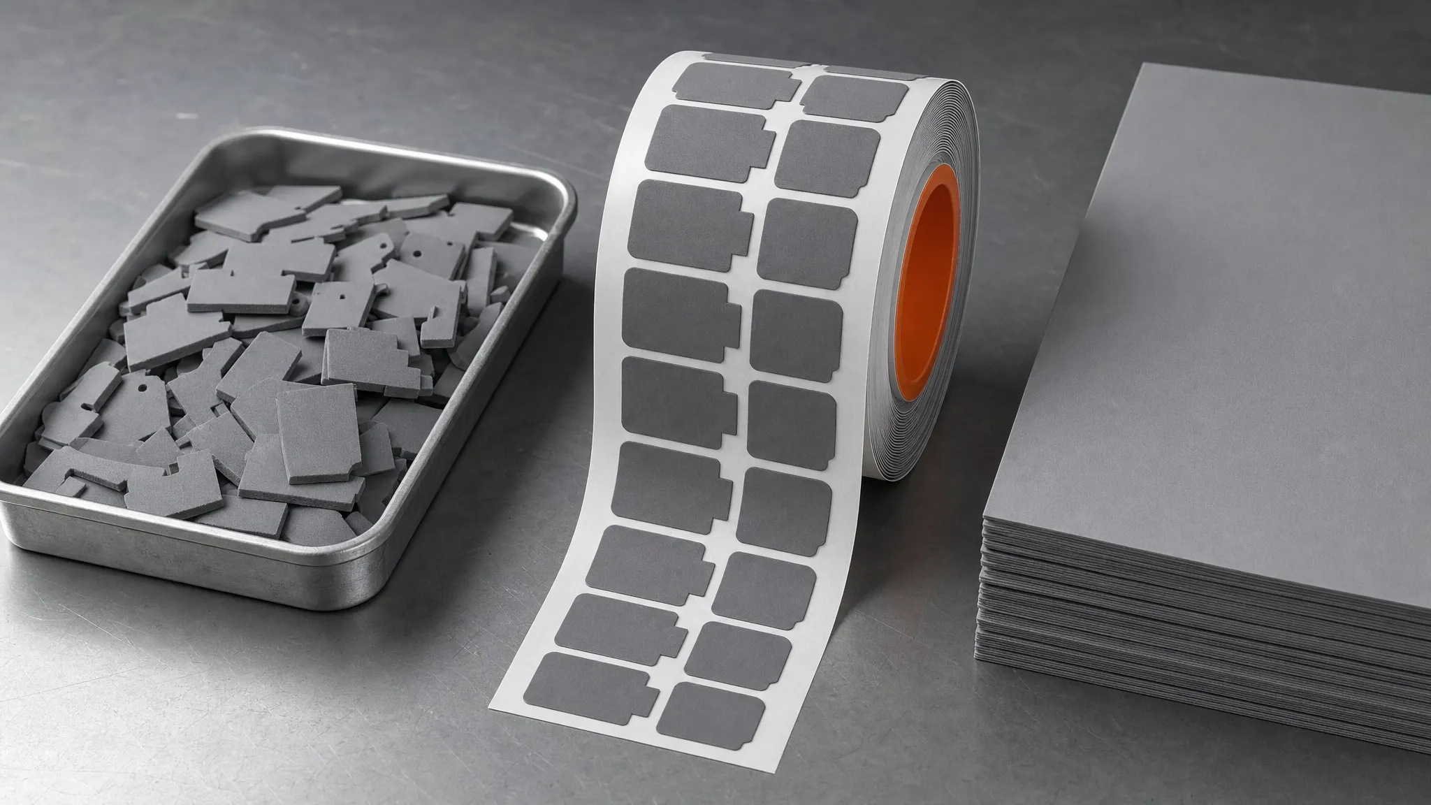
Supply format is a line-design decision, not a packaging detail: the same part arrives loose, on a liner, or on a roll.
ASTM F104 is worth knowing at this point in the conversation. It describes nonmetallic gasket materials by physical and mechanical properties rather than by name — a common language for suppliers and buyers. Its scope has a boundary that matters here: F104 covers cork, cellulose and similar materials with binders, and it excludes materials normally classified as rubber compounds, pointing them to Classification D2000, the family silicone foam belongs to. For the foam parts above, the vocabulary comes from the grade datasheet: compression stress at the working deflection and permanent compression set. Working from properties rather than from a material name is still how you avoid the situation where two suppliers both quote "silicone foam" and deliver parts that behave differently. If the finished part has to carry a flame rating, remember that the rating applies to the part configuration, not to the base material alone: UL 94 V-0 and VTM-0 flame ratings for TIMs explains why a thin-film rating is not interchangeable with a solid-part rating.
"Is die cutting more expensive?" is the question behind most price objections, and the answer depends on volume. A steel rule die is inexpensive tooling for short runs; a machined solid steel die costs more and lasts longer, and both are reusable for every order in the program. Die cutting wins on per-piece cost at production volume, with prototypes cut tooling-free and a steel rule die taking over once the geometry is frozen. Compare at your annual quantity, not at prototype quantity, and treat the die as a one-time cost per revision.
When a Die Cut Part Is the Wrong Answer
Four situations should send you to a different process:
- The stock itself has to be made to gauge. Below roughly 0.25 mm in a soft elastomer, die cutters generally expect the sheet to be skived — shaved as a thin uniform layer off a block — rather than moulded or cast, and that happens before any cutting. Treat 0.25 mm as an order-of-magnitude guide from shop experience, not a published threshold: the practical floor moves with the grade and with the tolerance you need, so confirm it with your converter. If gauge accuracy is the problem, the problem may not be die cutting at all.
- Walls, flanges or holes are smaller than the material thickness. Thin-wall geometry, very small holes and tight features need waterjet or digital knife cutting, which follow a tool path instead of a blade profile.
- The design is not frozen. If the outline may change next month, buy tooling-free cutting rather than a die that gets scrapped with the revision.
- The geometry is not flat, or the gap varies widely. Beaded and molded-in-place gaskets are molded, not cut; and across a large area with a widely varying gap, a dispensed liquid gap filler holds tolerance better than a fixed-thickness pad.
One more boundary: if the part seals a fluid joint — a flange, a pump, pipework — you are in a different discipline. Bolted-joint gaskets in cork, compressed fiber or flexible graphite are specified around bolt load and chemical compatibility, not thermal deflection. The rules here apply to flat cut parts in electronics and battery assemblies.
From Drawing to Validated Part
A die cut part is validated in three steps, and skipping the second is the usual reason a program ships a part nobody can explain.
- First article at assembly force. Measure the part in its installed condition, at the compression your process actually produces, not in free state on a bench.
- The application test, at that same compression. For a pad, measure thermal impedance or the resulting case temperature at the real bond line; for a seal, run the leak or ingress test at the installed deflection.
- Environmental cycling, then re-measure. Compression set and thermal drift surface here, not at first article.
If you would rather hand the constraints to someone who compresses these grades every day, ZIITEK's engineers will recommend a pad or gasket grade for your gap, force and compliance requirements, and send samples to test — start from the thermal pad product range.