Battery Pack Sealing: IP68 Silicone Foam Gaskets
How to seal an EV battery pack: six sealing interfaces, the pressure arithmetic behind a vent, compression force per metre, 15-year set, and leak-test proof.
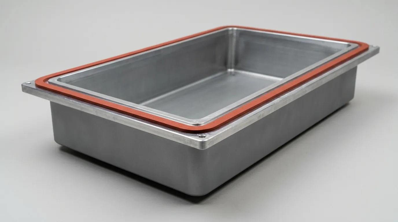
The Perimeter Gasket Is One of Six Sealing Interfaces
A pack closed at −10 °C and run at 60 °C develops about 27 kPa of gauge pressure — 3.3 tonnes spread over a 1.2 m² cover, all of it hunting the weakest fastener in the perimeter. That, not a datasheet, is the load a sealing system has to survive.
The water, when it arrives, usually enters somewhere other than the gasket: a connector whose IP claim was never carried to the pack, a vent thread seal that relaxed, or a joint that was never compressed evenly.
The framing to fix first is the gasket-selection one. Most of the literature treats battery pack sealing as a gasket selection question — pick a foam, pick a density, pick a width. It is a joint question. The gasket is one element in a load path running from the cover, through the fastener pattern and flange, into the housing, and out through every port, connector and vent that pierces the enclosure. Change the flange stiffness and you have changed the seal. Add a breather and you have changed the pressure it sees.
The rating belongs to the system, not the material. IEC 60529 splits IP68 into IP6X, dust-tight under the standard dust test, and IPX8, continuous immersion under conditions the standard leaves to be agreed between manufacturer and user. Nothing in that definition mentions silicone. A datasheet saying "IP68" is quoting a result taken on somebody's enclosure, with somebody's flange and fastener torque.
Four things therefore decide the outcome: which interface leaks, what pressure the seal is fighting, how much force the joint can deliver, and how the material behaves over fifteen years rather than twenty-two hours. This guide works through all four, with a die-cut closed-cell silicone foam gasket as the baseline — the format most pack programs specify for a serviceable cover. The rest of the pack's material stack is indexed in the EV battery thermal management hub.
Six Interfaces, Six Failure Modes
A pack is not sealed once. It is sealed six times, by six suppliers, and the gasket engineer usually owns two of them.
| Interface | What seals it | How it usually fails |
|---|---|---|
| Perimeter flange (housing to cover) | Die-cut closed-cell silicone foam, 3–8 mm | Uneven compression at corners and bolt bosses; set over thermal cycles |
| Serviceable cover or inspection lid | Foam gasket with pressure-sensitive adhesive, or a molded profile | Reused after service; adhesive creep; gasket displaced during refit |
| HV connector and busbar feedthrough | Molded seal or O-ring inside the connector | Mating-face damage, under-torque, connector IP claim not carried to the pack |
| Pressure relief vent / breather | ePTFE membrane in a molded body | Membrane wetted or blocked; vent body seal fails at its thread |
| Coolant inlet and outlet | O-ring or bonded seal in a fitting | Glycol attack on the elastomer; thermal relaxation; torque loss |
| Module and busbar level | Dispensed foam gasket (DFG) or foam sheet | Cell swelling compresses the foam past its usable deflection |
A pack can be IP68 at the flange and still fail, because the flange is the interface with the most design control: flat surfaces, known materials, a specified squeeze. The connector, vent and coolant fitting are bought-in parts with their own tolerances, handing the seal off to a mating geometry nobody on the pack team drew.
More importantly, only an interface-level specification can be verified. "IP68 gasket" is not a testable requirement. "Closed-cell silicone foam, 5.0 mm free thickness, 25–30% deflection at a 3.6 mm nominal flange gap, compression set ≤ 5% at 70 °C, water absorption < 0.1%, flame rating UL 94 V-0" is.
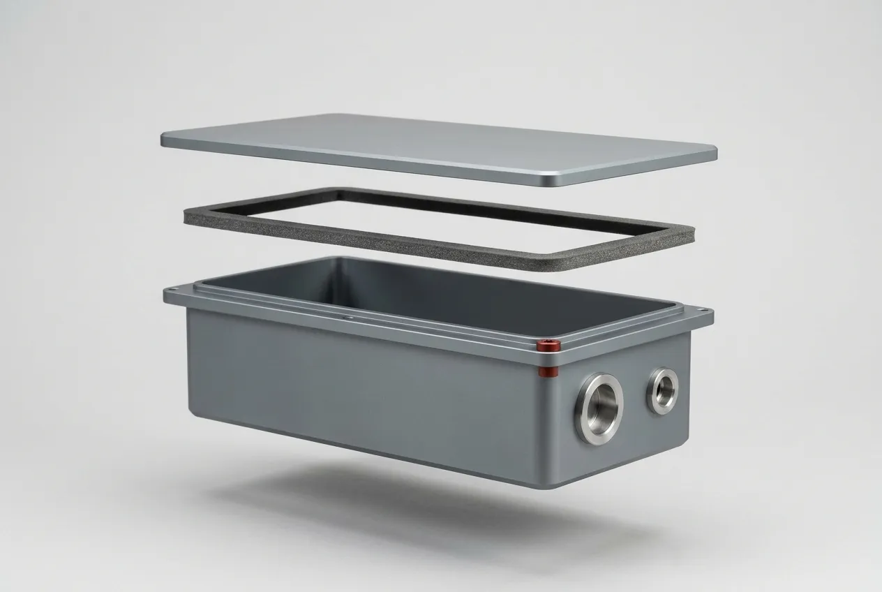
Washdown adds a duty immersion does not cover. Underbody steam cleaning is specified as IP6K9K from ISO 20653 — water at 80 °C and 80 to 100 bar, from 10 to 15 cm, for 30 seconds at each of four angles, as AEB's IP code explainer sets out. 9K does not imply 7 or 8: jet cleaning is not immersion, so a pack that meets a pressure washer needs both codes stated separately.
A Sealed Pack Is a Pressure Vessel. Design the Vent Into the Seal
The number that decides whether an IP68 battery pack needs a breather comes from the ideal gas law, not from sealing.
Hold volume fixed and change temperature. From −10 °C to 60 °C, absolute temperature runs from 263 K to 333 K, a ratio of 1.266. At constant volume the internal absolute pressure rises by the same ratio: 101.3 kPa becomes 128.3 kPa, a gauge pressure of about 27 kPa. Across a 1.2 m² cover that is 32 kN — roughly 3.3 tonnes pushing the cover off the gasket. Driving from sea level to a 2,000 m pass adds 22 kPa in the opposite direction, because ambient drops to about 79.5 kPa while the pack holds its own pressure.
No foam gasket is designed to hold that. A 27 kPa differential lifts a cover between fasteners, fatigues the gasket at the bolt bosses, and on the return stroke pulls a partial vacuum that can suck water past a seal that was fine in the lab. A sealed pack is not a sealed box; it is a pressure vessel with a designed leak path, and the engineering question is where that path sits.
The vent is the usual answer: an ePTFE membrane in a molded body, passing air at a few hundred millilitres per minute while holding water-entry pressure well above the immersion requirement. That converts the gasket's job from "hold pressure" to "hold water at near-zero differential" — a far easier and more durable requirement.
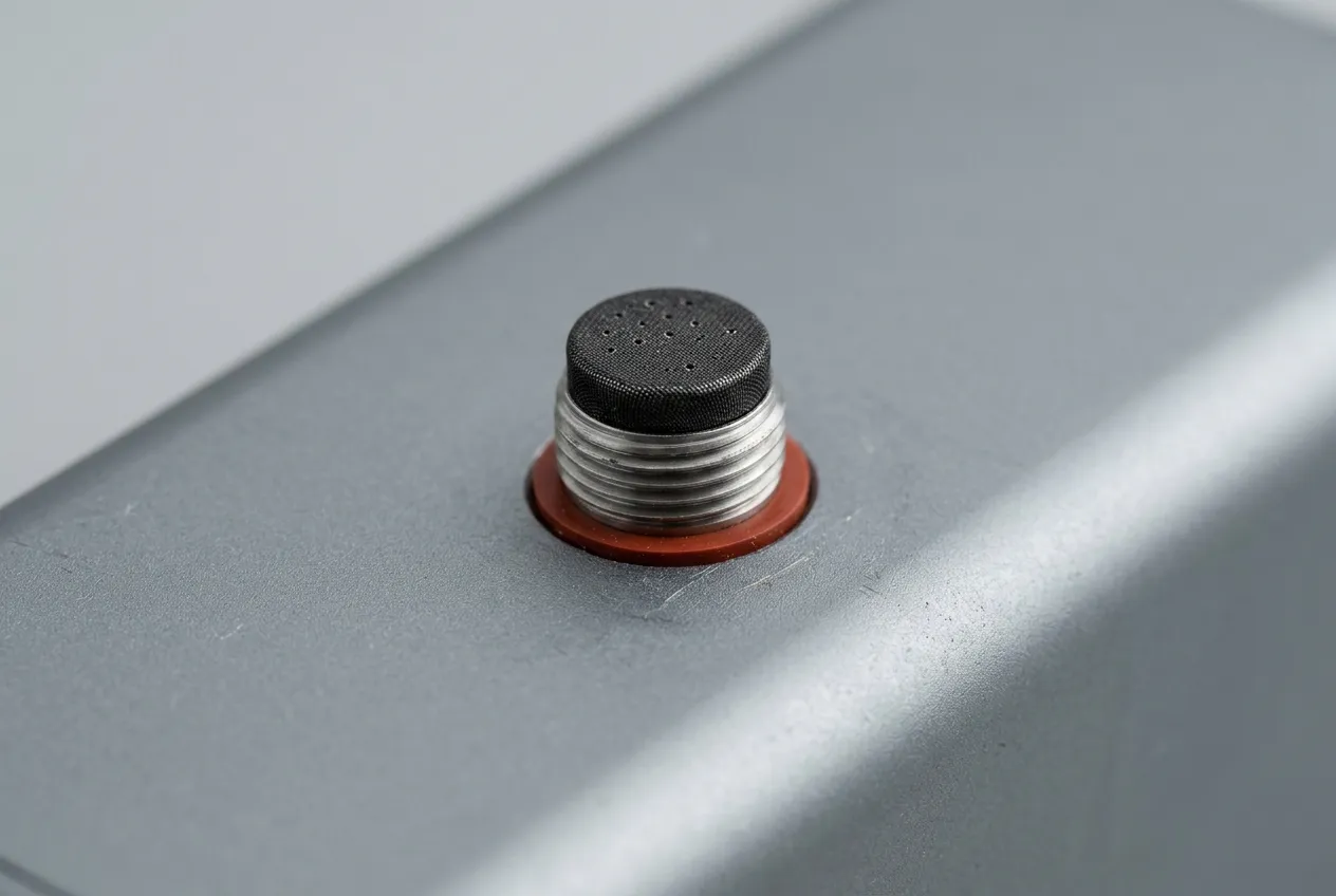
It also changes how the pack is tested, which is where specifications go wrong. Run the immersion test with the vent open and the pack equalises, so the gasket sees almost no differential and the pass proves little. Plug the vent port and you are testing an unvented vessel, which is not how the pack will live. The condition must be written down, and the acceptance criterion must name which configuration it applies to. SAE J3277, issued in April 2024, described leak-test methods for assembled packs, including the case where the coolant circuit is left in the loop.
Compression Force at Pack Scale: The Arithmetic Nobody Runs
Squeeze is a percentage, which makes it feel free. It is not: every percent of deflection costs force, and that force comes out of the cover and fasteners.
Take a mid-size pack: 4.5 m of seal path, a 6 mm wide gasket, closed-cell silicone foam in the soft-to-medium range. At 25% deflection the Z-FOAM®800 series publishes 20 to 110 kPa depending on grade.
| Stress at 25% deflection | Force per metre (6 mm wide) | Total clamp load over 4.5 m |
|---|---|---|
| 20 kPa | 120 N/m | 0.54 kN |
| 40 kPa | 240 N/m | 1.08 kN |
| 110 kPa | 660 N/m | 2.97 kN |
Solid silicone rubber typically needs 1 to 3 MPa at 25% deflection: 6 to 18 kN per metre, or 27 to 81 kN around the same perimeter. That is the argument for foam in one comparison. An M6 class 8.8 bolt at 10 N·m carries about 8.3 kN of preload, so the foam joint closes with a handful of fasteners while the solid-rubber joint needs a heavier cover, a denser bolt pattern and a heavier housing.
The second number is the one that gets missed: the squeeze the gasket sees is set by the flange gap, not its nominal thickness. Take 5.0 mm free thickness against a 3.6 mm nominal gap — 28% deflection, right in the band. Now apply the real tolerance. With ±0.8 mm of variation from weld distortion, casting flatness and fastener spacing, the same gasket runs from 12% deflection at a 4.4 mm gap to 44% at 2.8 mm.
At 12% a closed-cell foam may not close a continuous seal at all, particularly at a corner where two bead paths meet. At 44% it is crushed into its own cell walls, clamp load triples, and compression set accelerates for the rest of the pack's life. No single thickness clears both ends of a ±0.8 mm gap: a thicker foam lifts the 4.4 mm corner above the 12% floor and pushes the 2.8 mm corner further past 44%, a thinner one does the reverse, and 4.8 mm merely swaps a 12.0% floor for an 8.3% one. 5.0 mm already holds 12% at the 4.4 mm corner. That is why the flange, not the gasket, is the lever: stiffening ribs, closer fastener pitch or a machined land narrow the distribution itself; every millimetre of spread removed buys back squeeze at both ends.
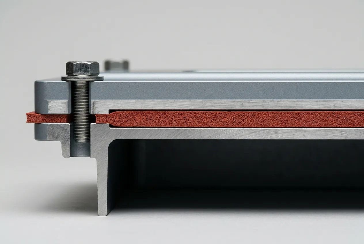
Most pack flanges are a flat land rather than a confined groove, which makes location the weak point: an unconfined foam frame can walk inward during cover fitment, and a gasket that has shifted 3 mm has lost the corner it was meant to seal. A pressure-sensitive adhesive backing, or a shallow locating step, is cheaper than the leak it prevents. Groove and squeeze logic is covered in the IP68 silicone foam gasket guide.
Compression Set Is a 15-Year Number, Not a 22-Hour One
Compression set decides whether the seal still exists at end of life, and it is usually quoted without one.
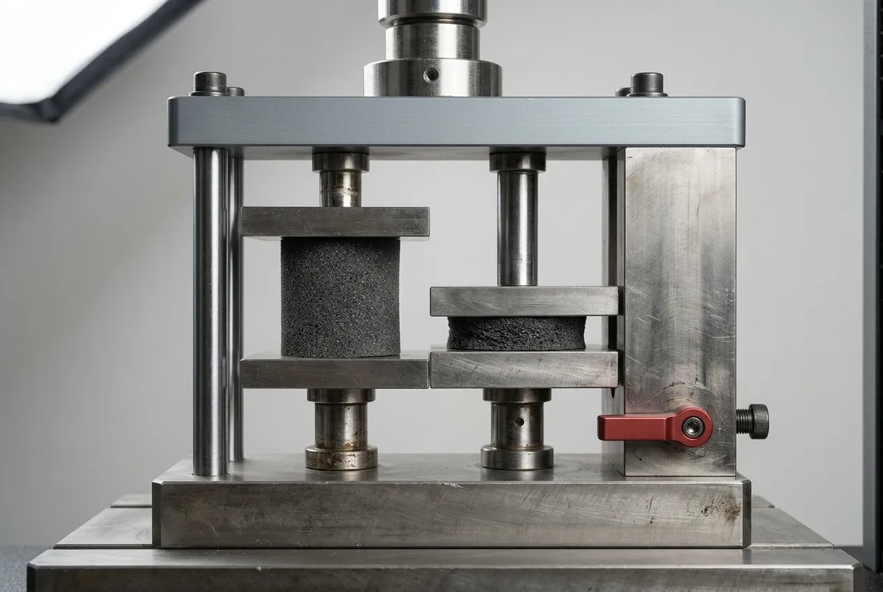
ASTM D395 Method B holds a specimen at fixed deflection — commonly 25% — for 22 hours at elevated temperature, releases it, and measures the thickness it failed to recover after 30 minutes. The result is the fraction of the original deflection that became permanent.
The translation follows the same definition. A 5.0 mm gasket compressed to 3.75 mm carries 1.25 mm of deflection doing the sealing work, and set is a fraction of that deflection, not of the free thickness: 5% removes 0.06 mm, so the gasket returns to 4.94 mm and the 3.6 mm gap leaves 27.1% squeeze. A 15% set, three times the Z-FOAM®800 limit, removes 0.19 mm, returns the gasket to 4.81 mm and leaves 25.2%. Neither ends the seal.
A few percent of D395 set is not what kills this joint. What kills it is that number at the temperature the part sees, on top of a flange gap that has drifted: 0.8 mm of gap error costs about 16 points of squeeze, five times what a 15% set costs. Set only moves the gasket further along a curve the gap already chose.
That is why the number needs its test temperature. Set measured at 70 °C describes a flange above a module running at 35 to 45 °C; between cells or beside a busbar joint, 110 °C is the honest condition, because set is strongly temperature-dependent. Z-FOAM®800 specifies 3 to 5% permanent set, density 0.2 to 0.42 g/cm³ and 20 to 110 kPa at 25% deflection; a competitor quoting "low compression set" with no temperature is not quoting a comparable number.
Flame behaviour is a separate test. UL 94 V-0 requires each specimen to stop burning within 10 seconds of both the first and second flame application, burning and afterglow to end within 30 seconds of the second, and no specimen to drip flaming material that ignites cotton — a material classification on a defined specimen, not a statement about a 5 mm gasket compressed 44% in a pack venting hot gas. Foam has its own ratings under the same standard, and the difference between HF-1 and V-0 is set out in the UL94 V-0 silicone foam article.
Pack-level requirements have moved too. China's GB 38031-2025 raises thermal-runaway requirements for high-voltage battery systems from July 2026 and, as E-Mobility Engineering's report notes, pushes the housing sealing system into the safety-critical path: the seal is now expected to hold back corrosive gas and pressure, not just water. Where the enclosure is qualified as an enclosure rather than a material, UL 50E assigns environmental Type ratings and tests factory-applied sealing compounds as part of that rating.
Die-Cut Foam, CIPG or FIPG: Decide by Serviceability First
Three processes compete for the same joint, and the argument usually starts in the wrong place. Start with the service question: will this joint be opened in service?
A formed-in-place gasket (FIPG) is dispensed onto one surface and the mating part is closed immediately, so the material cures in contact with both faces and bonds to both. A cured-in-place gasket (CIPG) is dispensed and cured before assembly, producing a compression gasket that can be separated and re-closed. Elkem's battery sealing overview describes both, and notes dispensed material has largely replaced pre-cut gaskets. Reading that as a rule for complex, high-volume geometry is this article's inference, not Elkem's — and it is exactly the case where serviceability does not apply, which is why the shift is not universal.
The dispensed chemistries split three ways: silicones, polyurethanes and butyls. Silicone dominates where the joint sees heat and flame, polyurethane is cheaper and tougher where temperatures stay modest, and butyl covers permanent low-cost seals that never need to be opened.
| Die-cut foam gasket | CIPG | FIPG | |
|---|---|---|---|
| Re-openable for service | Yes, without re-dispensing | Yes, as a compression gasket | No, destructive |
| Flange requirement | Flat land, adequate width, located | Flat, clean, primed | Flat, clean, primed |
| Complex 3D path | Poor — needs a 2D cut | Good | Good |
| Cure time in the cycle | None | Hours to days off-line | In-line or off-line |
| Capital | Die tooling only | Dispensing cell + curing | Dispensing cell |
| Bonded to both faces | No | No | Yes |
The FIPG advantage is adhesion, and under thermal runaway that is real: Wevo's WEVOSIL 23130 LSR, cited in the same report, claims over 2 MPa of adhesion — what keeps a seal intact when internal gas pressure spikes and a compression gasket would be pushed off its land. If the joint must never open and the pack vents through a dedicated valve, FIPG is the stronger choice.
Foam needs no cure, no dispensing cell and no primer, and it survives being opened. A pack with a serviceable cover, an inspection lid over the BMS, or low-to-mid volume is usually better served by a die-cut closed-cell foam frame, because capital and process control cost more than the part.
The material still has to be right. Silicone is the default for temperature range and set; EPDM foams sit above 15% set and lose force faster, which is why the rubber vs silicone gasket comparison puts silicone ahead for any joint that sees thermal cycling. And only closed-cell foam holds water at all, as the open-cell vs closed-cell comparison sets out.
Verify the Claim: Battery Pack Leak Test, Four Tests and Five Documents
Qualifying a pack seal means running four tests and collecting five documents.
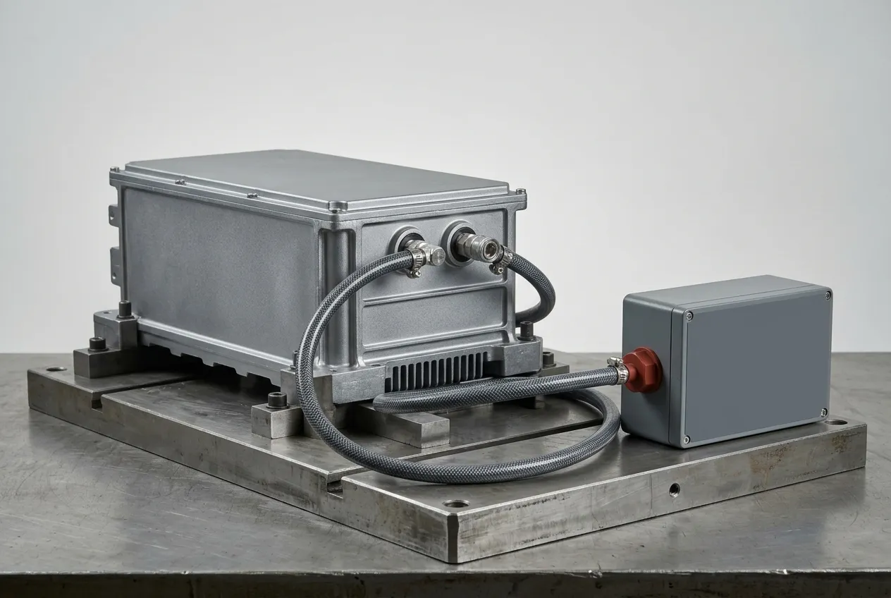
Immersion, with the conditions stated. IPX8 has no fixed depth or duration in IEC 60529; they are agreed. Write yours down — 1.5 m for 30 minutes, say — and require the report to state the same numbers, plus whether the vent was installed and open.
Production leak test, correlated to the immersion result. Immersion is not a line test: IP67's 30 minutes at 1 m is a destructive sample test, and an agreed IPX8 condition is more severe — deeper, longer, or both. Assembled packs are tested by pressure decay or tracer gas, and SAE J3277 describes the methods. This matters beyond procedure — SAE's account of the standard's origin cites an estimated 3,000 to 5,000 EVs that took on water during Hurricane Ian in 2022, roughly 600 written off and about 36 that went into thermal runaway; Idalia in 2023 caused further fires at lower numbers. Ask what leak rate the acceptance limit corresponds to, in cubic centimetres per minute at a stated pressure.
Compression set on the production lot, at the application temperature. A lab sample is not a lot result. Require D395 Method B data at the joint's service temperature and, for cell-adjacent parts, at 110 °C.
Pressure cycling before the leak test. Five hundred thermal cycles between the pack's cold and hot extremes, then re-test leak rate and re-measure gasket thickness. This is the test that finds a 12% squeeze corner.
The documents: a UL Yellow Card number you can look up yourself (ZIITEK's covers Z-FOAM®800 — listed as Z-FOAM8 on the card — under file E331100), an IATF 16949 certificate with a current validity date, an IP68 report with the conditions written into it, a first-article dimensional report on the gasket, and lot traceability back to the compound batch.
What to Put in the RFQ
A battery pack gasket RFQ that produces comparable quotes states: seal path length and width; free thickness and target deflection band; the flange gap distribution, not just the nominal; compression set at service temperature; water absorption; flame rating with specimen thickness; adhesive backing and position; the IP codes required and their test conditions; annual volume and the service events expected over life.
Two are usually missing, and they cause most returns: the gap distribution, and how often the joint will be opened. A gasket specified for one assembly and opened four times in service is a different part.
Custom die-cut foam gaskets are cut from sheet or molded to a frame, so the cut edge and dimensional tolerance are part of the seal — the die-cut gasket specification guide covers what to hold a converter to. Where the same seam must also survive a thermal event, the choice overlaps with thermal runaway containment, and the gasket should be selected against both duties at once.
Send the drawing, gap data and test conditions to ZIITEK's application engineers and the answer should be a material grade, a thickness, a force per metre and test reports — not a datasheet.