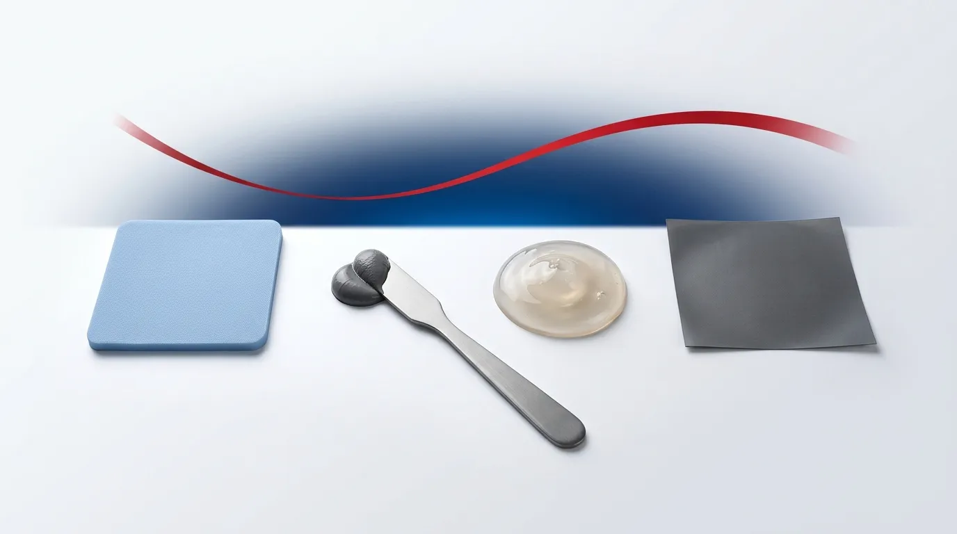
What Is a Thermal Pad? How They Work, Types & W/mK
A thermal pad is a soft, pre-cut thermal interface material that fills the gap between a chip and heatsink. Learn how they work, W/mK, types and how to choose.
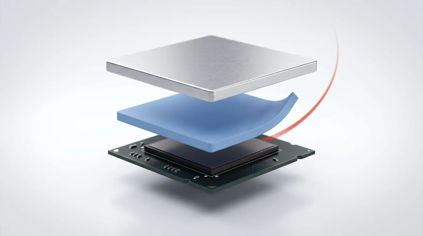
A thermal pad is a soft, pre-formed sheet of thermally conductive material placed between a heat-generating component and a heatsink or chassis. It fills the microscopic air gaps between the two surfaces so heat can flow across the joint instead of being trapped by insulating air. It is one type of thermal interface material (TIM), alongside thermal paste, gels, and phase change materials. On datasheets and in catalogs the same part is also called a thermally conductive pad, a thermal interface pad, or a gap pad — the terms are interchangeable.
Unlike paste, a thermal pad arrives at a fixed thickness and hardness. That makes it clean, repeatable, and ideal for bridging large or uneven gaps — but it also means the pad only performs when it is specified and compressed correctly. This guide explains what thermal pads are, how they work, what each material type is good for, and what the numbers on a datasheet — W/mK, impedance, Shore hardness — actually mean once the pad is in your stack-up. It is written by the engineering team at ZIITEK, a thermal-management-materials manufacturer that has supplied pads, greases, and gap fillers to EV, telecom, server, and LED customers since 2006.
What does a thermal pad do?
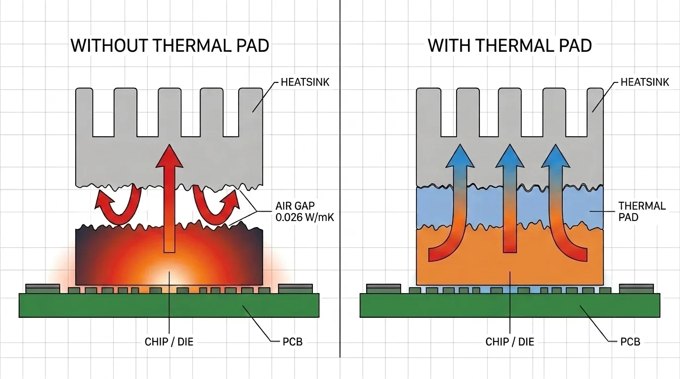
Two metal surfaces that look flat are, at a microscopic level, rough. Press a chip against a heatsink and they only touch at a few high points; the rest of the interface is air. Air conducts heat poorly — about 0.026 W/mK at room temperature — so those gaps act as insulation and drive the component’s junction temperature up. Even a modest 1–3 W/mK pad conducts roughly 40–100× better than the air it displaces.
A thermal pad solves this by deforming to fill those voids. Because it is soft and compressible, it “wets out” against both surfaces, displacing the air and creating a continuous conductive path from the hot component to the cooler heatsink. The result is lower thermal resistance across the joint and a cooler, more reliable part.
Most thermal pads do a second job at the same time: electrical insulation. Silicone-based pads are dielectric, so they let heat pass while keeping a component electrically isolated from a grounded heatsink — useful around MOSFETs, VRMs, and power ICs.
How does a thermal pad work?
The mechanism is conduction across a filled gap:
- Contact & conformance — under mounting pressure, the pad compresses and conforms to both mating surfaces, eliminating trapped air.
- Conduction — heat moves from the die, through the pad’s conductive filler network, into the heatsink.
- Steady state — the pad holds its shape and position over years of thermal cycling, unlike paste, which can migrate.
The pad body is usually a silicone (or silicone-free) elastomer loaded with conductive fillers — aluminum oxide, zinc oxide, boron nitride, graphite, or ceramic particles — that carry the heat. The more (and better-connected) the filler, the higher the conductivity, but also the stiffer and denser the pad. Every pad is a balance between conductivity, softness, and manufacturability.
What is a thermal pad made of?
| Base / filler | Typical role | Trade-off |
|---|---|---|
| Silicone elastomer | Most common carrier; flexible, wide temperature range, dielectric | Can outgas low-molecular-weight siloxanes in sensitive optics |
| Silicone-free (e.g. ZIITEK Z-Paster®) | For optics/relays where siloxane outgassing is a risk | Often narrower temp range |
| Aluminum oxide / zinc oxide filler | Inexpensive conductivity boost | Higher loading = stiffer pad |
| Boron nitride | High conductivity with low dielectric constant | Higher cost |
| Graphite / carbon fiber | Highest conductivity, thin pads (ZIITEK’s TIR®700: 9–35 W/mK) | Electrically conductive — not an insulator |
This matters for selection: a “silicone thermal pad” and a graphite pad can both be called thermal pads, yet one insulates and one conducts electrically. Always check the datasheet, not just the W/mK number.
Thermal pad vs thermal paste (vs grease vs putty)
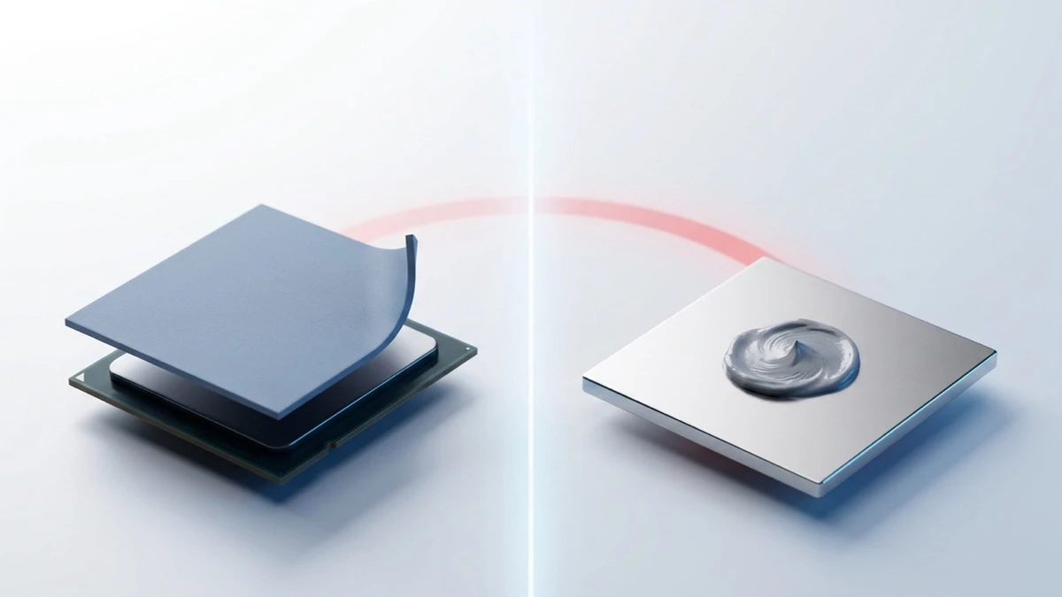
This is the comparison every reader wants, so here it is up front. For the full breakdown see thermal pad vs thermal paste.
| Thermal pad | Thermal paste | |
|---|---|---|
| Form | Solid, pre-cut sheet | Viscous compound |
| Best for | Larger/uneven gaps, multiple components | Tight, flat CPU/GPU lids |
| Bulk conductivity | ~1–18 W/mK (carbon-fiber pads reach ~35) | ~1–14 W/mK |
| Bond line achievable | Thicker (0.2–20 mm) | Very thin (tens of µm) |
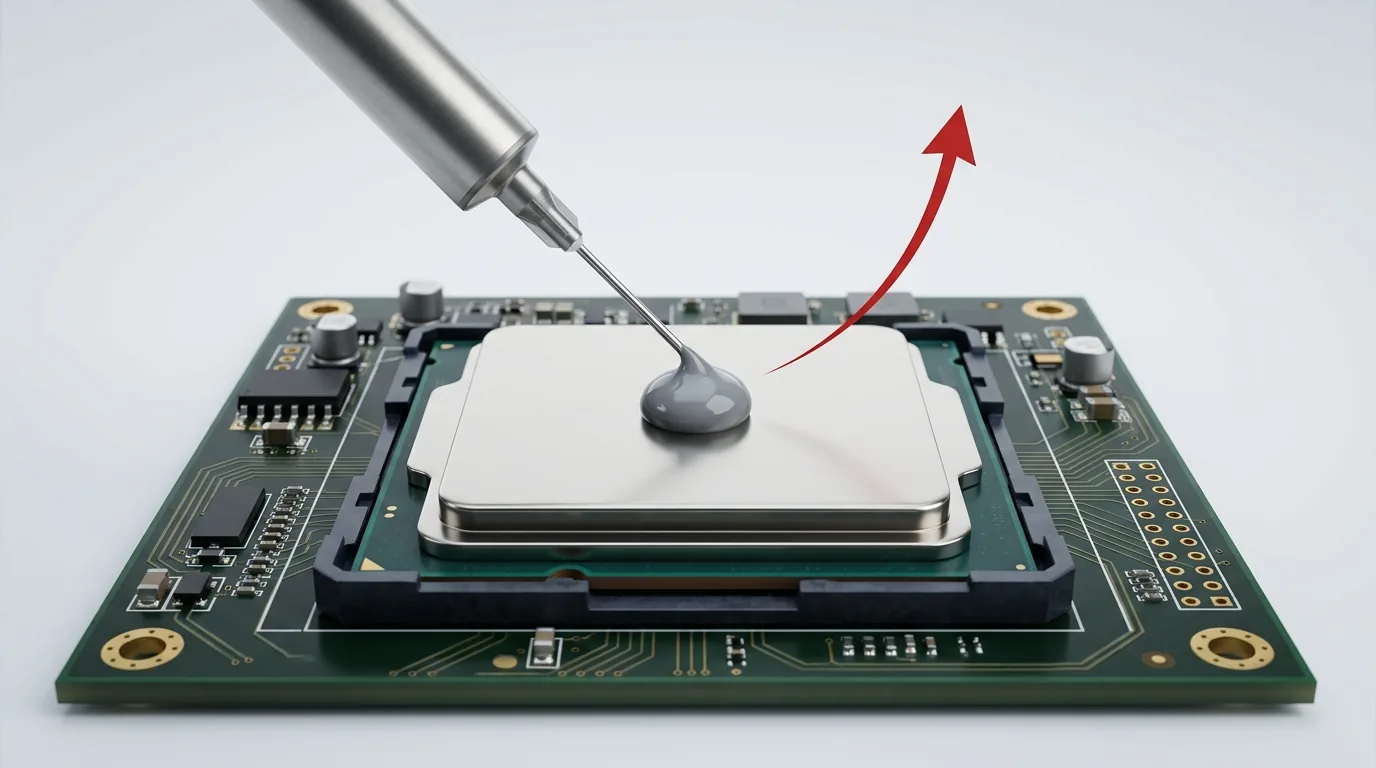
| Cleanliness | Clean, no mess, reusable | Messy, single-use |
| Assembly | Fast drop-in, automatable | Requires dosing skill |
| Long-term | Stable, no pump-out | Can dry out / pump out |
The short version: use a pad when you need to span a real gap, insulate, or assemble at volume; use paste when the two surfaces are flat and nearly touching and you want the absolute lowest resistance. For flexible, dispensable filling of very large or varying gaps, a gap filler or phase change material may beat both.
Thermal conductivity and W/mK: how to read a thermal pad spec
The headline number on any pad is its thermal conductivity in W/mK (watts per meter-kelvin) — how well the bulk material moves heat. Higher is better, all else equal.
To put real numbers against that, here are our own catalog ranges rather than vague industry averages. ZIITEK’s TIF® silicone pads run 1.25–18 W/mK; our boron-nitride TIF®100N pads 1.5–5.0 W/mK; our silicone-free Z-Paster®100 pads 1.5–10 W/mK; and our TIR®700 carbon-fiber pads 9–35 W/mK. These are ZIITEK grades, not an industry survey — other manufacturers’ ranges will differ, so read the datasheet for the part you are actually buying. The wide spread is the point: “thermal pad” spans more than an order of magnitude in conductivity, and the top of that range comes from carbon fiber, not silicone.
But here is the trap engineers fall into: bulk W/mK does not equal real cooling performance. What actually determines the temperature drop across the joint is thermal impedance — which folds in bond line thickness and the contact resistance at each surface. A 6 W/mK pad that conforms well under low pressure can outperform a stiff 12 W/mK pad that won’t wet out. We unpack this fully in understanding thermal conductivity (W/mK) in TIM — read it before you spec on W/mK alone.
Two more numbers worth knowing:
- Thermal impedance (°C·in²/W or K·cm²/W) — the real-world resistance of the pad at a given thickness and pressure. Lower is better. It is characterized under ASTM D5470, the standard test method for the thermal transmission properties of thermally conductive electrical insulation materials — if a datasheet quotes impedance without naming a thickness and pressure, the number is not comparable to anyone else’s.
- Dielectric / breakdown voltage — how much voltage the pad withstands before it conducts. Values are specific to the grade: ZIITEK’s TIS® thermally conductive insulating materials, for instance, are rated 1500–6000 VAC. Check it if the pad sits near live traces — and note that graphite and carbon-fiber pads are not insulators at all.
Thermal pad thickness: how to choose and measure
Thickness is where thermal pads are most often specified wrong. The rule of thumb: the pad’s nominal (uncompressed) thickness should slightly exceed the measured gap, so that assembly compresses it 20–30%. Compression is what forces the pad to wet out; an uncompressed pad barely works.
Rough thickness bands for common gaps:
| Measured gap | Typical nominal pad thickness |
|---|---|
| Very tight (component nearly touches heatsink) | 0.5–1.0 mm |
| Moderate | 1.5–2.0 mm |
| Large / stepped (VRAM, tall components) | 3.0–5.0 mm |
To measure the gap accurately, assemble the heatsink with a soft modeling putty or a thickness gauge in place of the pad, disassemble, and measure the crush height at each component. Choosing thickness, compression ratio, deflection force, and Shore hardness together is its own discipline — the full method (with datasheet reading and mounting-pressure limits) lives in our thermal pad thickness & compression guide.
A note on hardness: pads are rated in Shore OO (softest, e.g. 5–70) or Shore A. Softer pads conform under lower pressure and protect fragile components; harder pads hold shape but need more clamping force. ZIITEK’s TIF® silicone pad line, for example, spans roughly 1.25–18 W/mK, 0.25–12 mm thickness, and 5–70 Shore OO — the range exists precisely because no single pad fits every gap.
Types of thermal pad
- Silicone gap pad — the default. Dielectric, wide temperature range; ZIITEK’s TIF® line covers 1.25–18 W/mK.
- Silicone-free pad — for optics, cameras, and relays where siloxane outgassing must be avoided; ZIITEK’s Z-Paster®100 runs 1.5–10 W/mK.
- Graphite / carbon-fiber pad — the conductivity ceiling for pads, and thin and light with it: ZIITEK’s TIR®700 carbon-fiber pads reach 9–35 W/mK and work at low clamping pressure. The catch is electrical: they are non-insulating, so they cannot sit across live traces the way a silicone pad can.
- Boron-nitride pad — high conductivity with a low dielectric constant, for RF-sensitive designs; ZIITEK’s TIF®100N covers 1.5–5.0 W/mK.
- Phase change pad — solid at room temperature, softens at operating temperature to flow like paste; see what is phase change material (PCM).
A “gap pad” is just a thermal pad doing one job
You will see the term gap pad or thermal gap pad used interchangeably with thermal pad. Strictly, a gap pad is a thermal pad chosen specifically to fill a defined air gap between a component and an enclosure or heatsink — the emphasis is on conforming to that gap at low stress. If your design has a genuine, repeatable gap to span at volume, a gap pad is usually the right sourcing term.
Where it gets confusing is the neighboring category: a gap filler is dispensed as a liquid and cures or stays soft in place, rather than arriving pre-cut. Pads win on cleanliness and drop-in assembly; fillers win on wildly varying gaps and near-zero mounting stress. We compare all three formats side by side in gap filler vs gap pad vs phase change.
How to choose a thermal pad: a selection checklist
Work through these in order — it mirrors how a design engineer specs a TIM. For the full material-agnostic framework see how to choose a thermal interface material.
- Measure the gap (and its tolerance across units). This sets thickness.
- Set the required conductivity from your power dissipation and temperature budget — don’t over-buy W/mK you can’t use.
- Check electrical needs — must the pad insulate (silicone) or conduct (graphite)?
- Pick a hardness that your mounting pressure and component fragility allow (Shore OO for delicate parts).
- Confirm reliability — operating temperature range, compression set, outgassing, flammability (UL 94 V-0 for most electronics).
- Match the format — sheet, die-cut, or adhesive-backed for your assembly line.
Applications: where thermal pads are used
CPUs and GPUs, VRAM and memory modules, MOSFETs and VRMs, M.2/NVMe SSDs, LED modules, power-supply and battery packs, telecom and 5G radios, EV and energy-storage electronics, and automotive control units. In practice, wherever a component sits a small, defined distance from a cooling surface — and especially where insulation or clean high-volume assembly matters — a thermal pad is the go-to interface.
Frequently asked questions
Do thermal pads actually work? Yes — especially for low-to-moderate power parts, uneven gaps, and multi-component boards. For a flat, high-power CPU lid where you can achieve a near-zero bond line, paste still gives lower resistance. Match the material to the joint.
Is a thermal pad better than thermal paste? Neither is universally better. Pads win on gap-filling, cleanliness, insulation, and assembly speed; paste wins on minimum thermal resistance for flat, tight interfaces. See the full comparison.
What thickness thermal pad do I need? Measure the gap, then pick a nominal thickness slightly greater so assembly compresses the pad ~20–30%. Too thin and it won’t contact both surfaces; too thick and it over-stresses the component.
What does W/mK mean on a thermal pad? It is the bulk thermal conductivity of the material. Higher is generally better, but real cooling depends on thermal impedance at your actual thickness and pressure — not W/mK alone.
How long does a thermal pad last? Quality silicone pads typically last the life of the device — often 3–5+ years. Good paste can last just as long, so the honest advantage is not raw lifespan but failure mode: a pad cannot dry out, pump out under thermal cycling, or migrate off the die the way grease can, so its performance degrades more predictably. Excess heat, over-compression, and poor-quality fillers shorten that.
Getting the pad right
A thermal pad is deceptively simple: a soft sheet that fills a gap. But its value only shows up when thickness, conductivity, hardness, and compression are specified together for your joint — which is exactly where generic advice stops and engineering begins. Start from the TIM selection guide for the whole landscape, and if you’re specifying pads into a product at volume, ZIITEK’s engineering team can help match a pad’s conductivity, thickness, and hardness to your design and send samples to validate.
Sources: Thermally conductive pad — Wikipedia for the naming conventions and materials background; Thermal conductivity and resistivity — Wikipedia for the 0.026 W/mK conductivity of air; ASTM D5470 for the standard test method behind quoted thermal-impedance figures. All product specification ranges (TIF®, TIF®100N, TIR®700, TIS®, Z-Paster®100) are ZIITEK’s own catalog values, not industry averages.