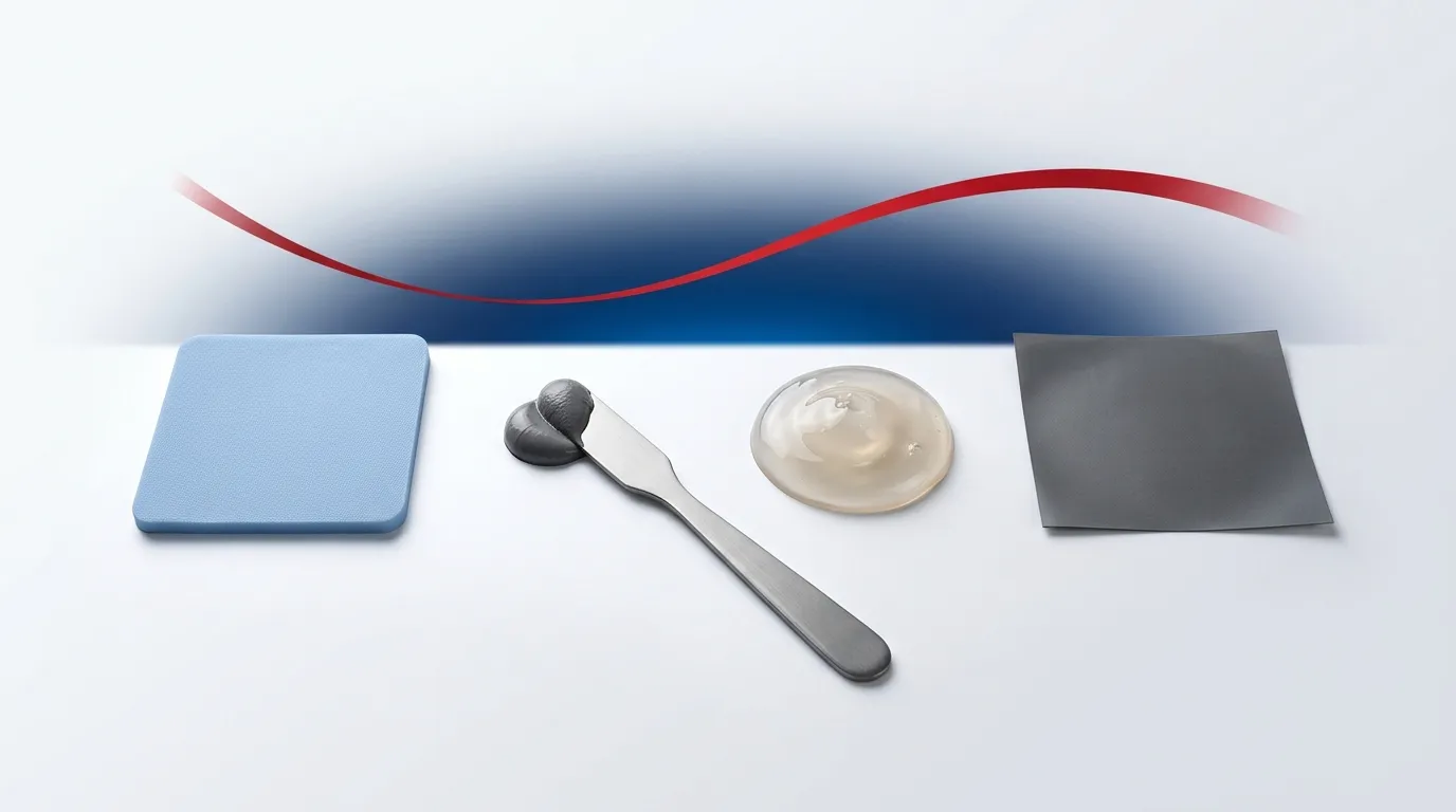
Thermal Pad vs Thermal Paste: Which Should You Use?
A practical comparison of thermal pads and thermal paste — how each works, where each wins, and how to choose by gap size, W/mK and manufacturability.
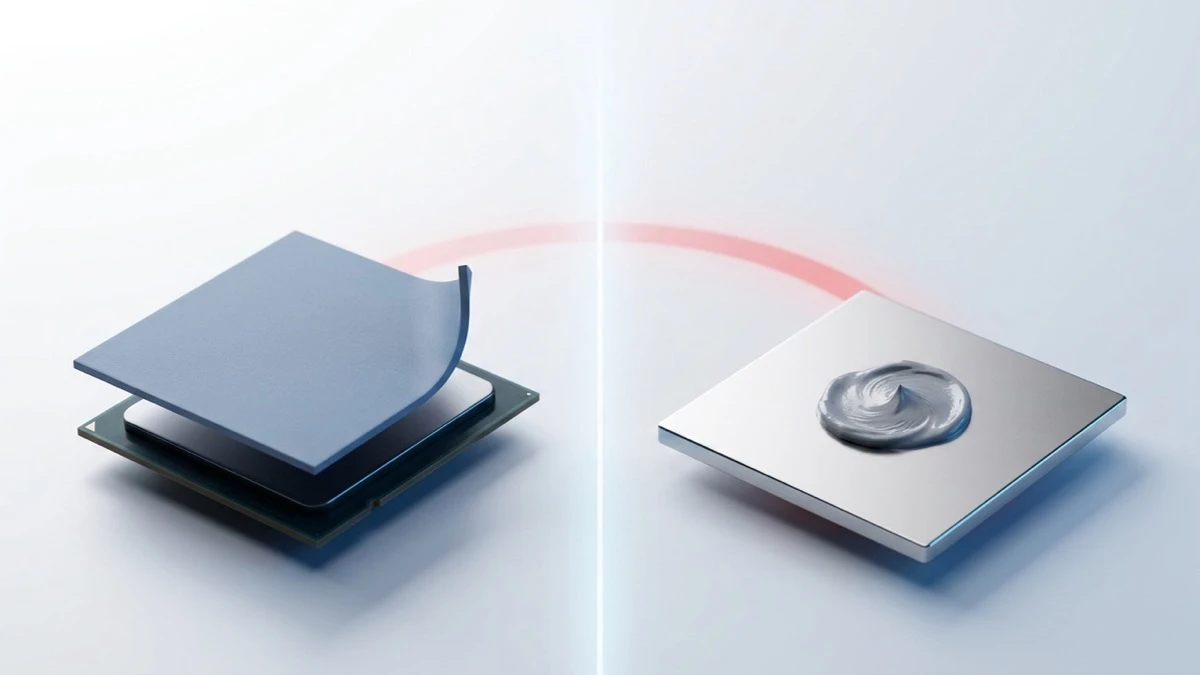
Short answer: use thermal paste when a chip sits directly against a flat heatsink and you want the lowest possible temperature — paste squeezes down to a razor-thin layer that conducts heat better than any pad. Use a thermal pad when there is a measurable gap to fill, several components of different heights to cool at once, or you want a clean, reusable, no-mess install. Neither is universally “better”; they solve different mechanical problems.
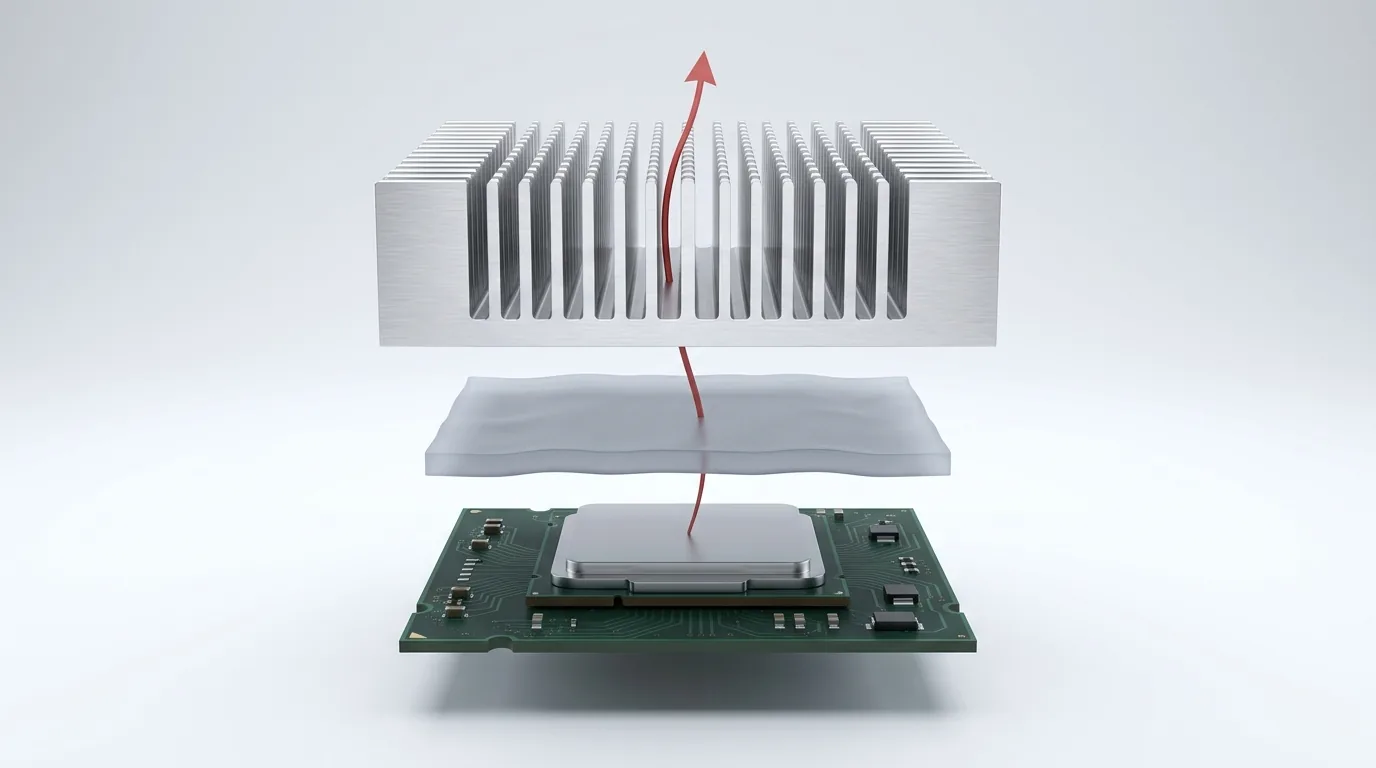
Both are thermal interface materials (TIMs) — the layer that lives between a hot component and its cooler. Their job is identical: push heat across the tiny air-filled valleys between two surfaces, because air is a terrible conductor.
It is worth putting a number on “terrible,” because it is the number that makes this whole comparison make sense. Air conducts at roughly 0.026 W/mK. Even the most ordinary silicone gap pad, at 1.25 W/mK, moves heat about 50× better than the air it displaces. That gap is why any TIM beats no TIM by a mile — and it is also why the pad-vs-paste argument is a fight over the last few percent, not the first 98. Where the two differ is how they close that gap, and that difference decides which one belongs in your build.
This guide compares them the way a materials engineer would — dimension by dimension — then gives you a decision you can actually apply. We will keep the numbers honest and point out where each material genuinely loses.
A disclosure up front: ZIITEK manufactures both sides of this comparison — gap pads and thermal grease alike. We have no format to defend, so this article is free to tell you where each one genuinely loses.
The two materials in one paragraph each
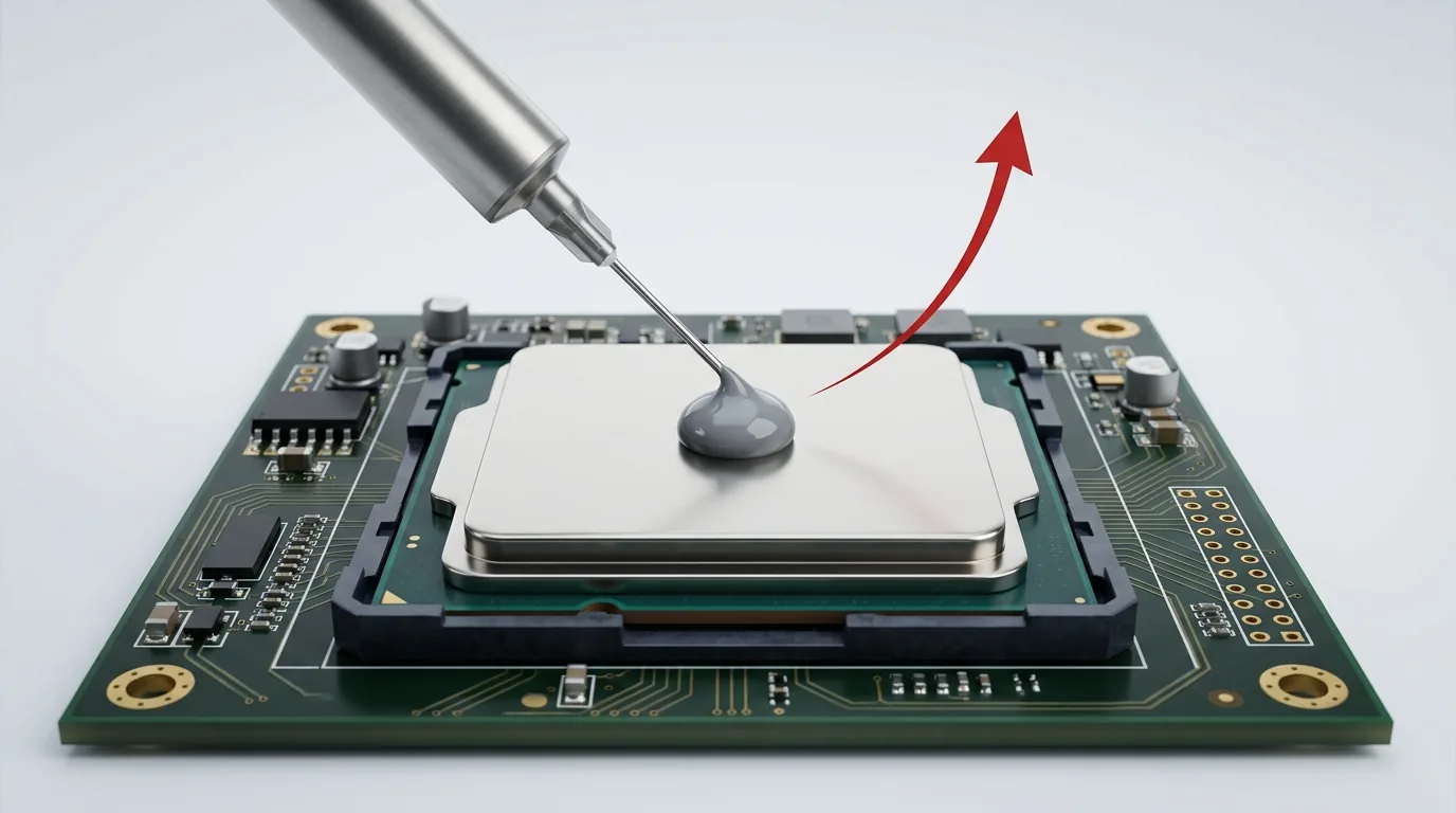
Thermal paste (also called thermal grease or compound) is a viscous fluid: a silicone or oil base loaded with conductive particles such as zinc oxide, aluminum oxide, or boron nitride. Because it is a liquid, it flows into microscopic surface scratches and then gets pressed down to a very thin film when the cooler is clamped on. Read the full breakdown in what is thermal paste.
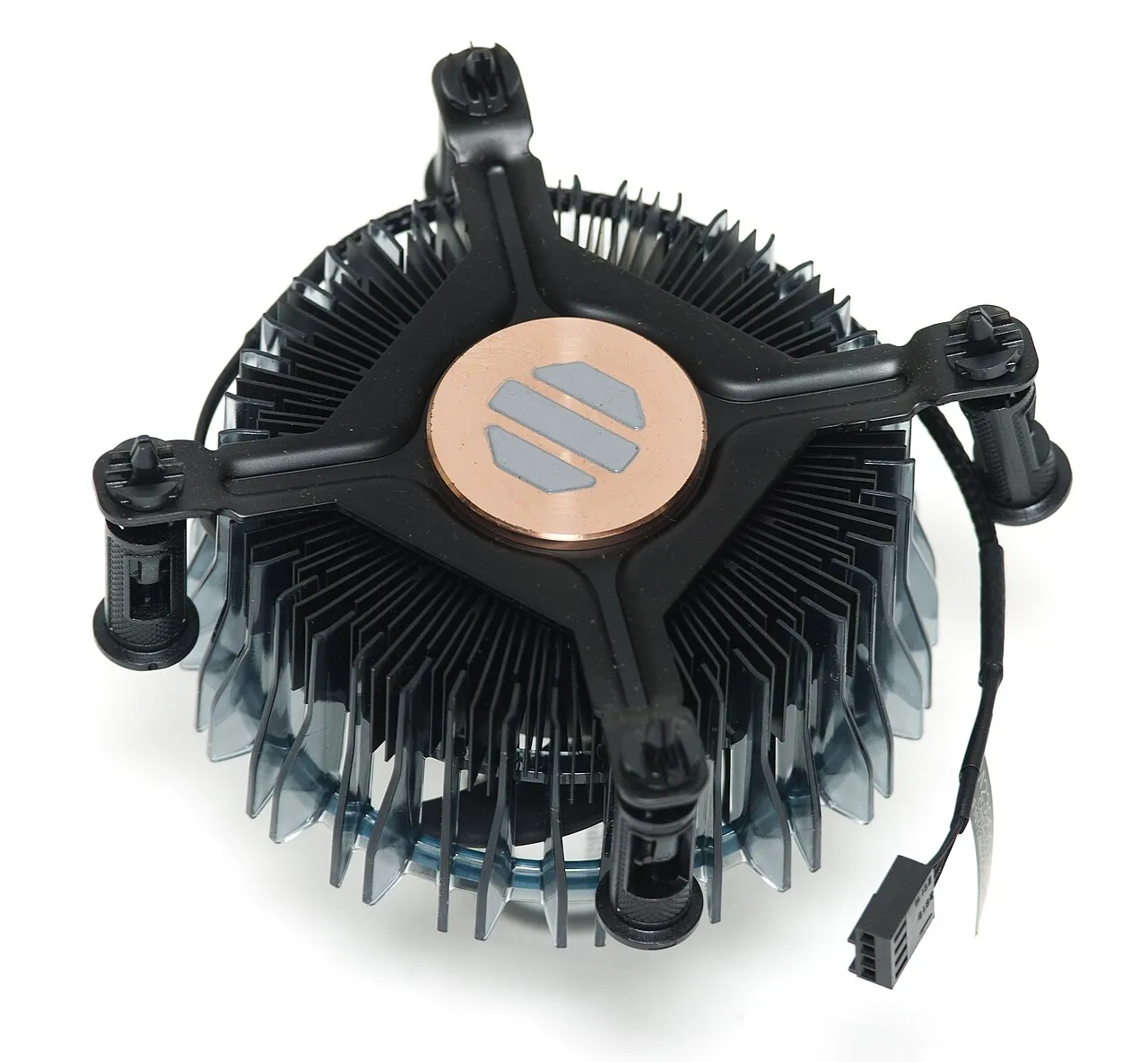
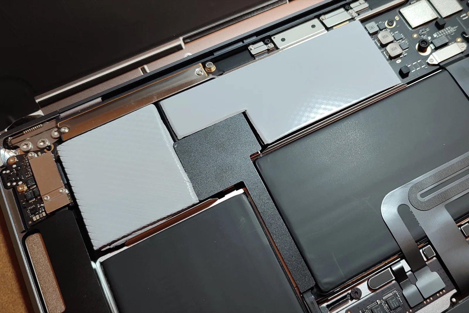
A thermal pad is a solid, pre-formed sheet of conductive silicone (sometimes carbon-fiber or graphite filled) cut to a specific thickness. You peel it, place it, and clamp it — no cure, no mess. It compresses slightly to conform to a surface but keeps its shape, so it can bridge a real physical gap. See what is a thermal pad for thickness and selection detail.
Dimension 1: Thermal performance
On raw heat transfer across a flat, direct contact, paste wins — and it is not especially close. A good paste presses to a bond line only tens of microns thick — the bond line thickness, or BLT — so even a modest bulk conductivity translates into low thermal resistance.
To keep the numbers honest, the ranges below are our own product lines rather than vague industry averages: ZIITEK’s TIG®780 thermal grease runs 1.0–5.2 W/mK, our TIF® silicone gap pads 1.25–18 W/mK, TIR®700 carbon-fiber pads 9–35 W/mK, and liquid-metal TIM 35–58 W/mK. Other manufacturers’ grades will differ, and specialist pastes are quoted higher than ours — always read the datasheet you are actually buying.
Notice what that does to the easy assumption: on bulk conductivity alone, our pads out-spec our own paste. Yet paste still wins the flat joint — which tells you bulk thermal conductivity (W/mK) is only half the story. What actually cools your chip is thermal resistance, which depends on the bond line thickness too. A pad is far thicker than a squeezed-down paste layer, so on a flat CPU lid the pad’s thicker bond line usually gives it away. This is also why thermal resistance and thermal impedance are the numbers engineers actually spec against, not W/mK alone. Bulk conductivity is a material property; resistance is what your heatsink feels.
It is also why the industry does not compare TIMs on W/mK alone. The standard method, ASTM D5470, clamps a sample between two reference bars and measures the heat actually crossing it at a known thickness and pressure — so what you get out is resistance for a real bond line, not a bulk figure from a datasheet. If you are comparing two materials, compare them there.
Verdict: For a flat die-to-heatsink joint, paste transfers heat better. Pads close the gap only when their high-conductivity grades meet a genuine air gap that paste could never fill.
Dimension 2: Filling gaps and surface conformity
This is where the tables turn. Paste is a thin-bond-line material — brilliant at erasing microscopic roughness, useless at spanning a real gap. Try to fill a 1 mm gap with paste and you get a thick, sagging, poorly performing blob: the same fluidity that lets it flow into scratches is what stops it holding a millimetre of standoff.
A pad is built for gaps. It comes in defined thicknesses — commonly 0.5 mm up to 5 mm and beyond — so it can bridge the space between, say, a graphics card’s memory chips and a cooler’s cold plate, where the components sit at different heights. Pick the right pad thickness and compression and it conforms to both surfaces at once.
Verdict: Any gap larger than “polished-metal roughness” is pad territory. Paste has no answer here.
Dimension 3: Application, mess, and skill
Pads are the forgiving option. Peel, place, clamp — done. There is no “too much,” no spillage onto the board, and no technique to learn, which is why pads dominate high-volume assembly lines and repairs on multi-component boards.
Paste demands a bit of care. Too little starves the contact; too much can ooze over the edges. It is not hard — see how to apply thermal paste correctly — but there is a right amount and a right method, and a first-timer can get it wrong.
Verdict: Pads win on ease and repeatability. Paste rewards a careful hand.
Dimension 4: Reusability, rework, and longevity
Pull a heatsink off a pad and, in many cases, you can reseat it — the pad survives. Paste is single-use: once you break the joint you must clean off the old compound and reapply.
Longevity is more nuanced, and both materials have a real failure mode — this is not a case of one lasting forever. Paste can suffer pump-out (repeated heat cycles slowly push it out of the joint) and dry-out (the carrier evaporates over years), which is why paste is a maintenance item. Pads are dimensionally stable and do not pump out, but they can take a compression set — losing a little thickness and springiness after long compression at temperature. Quality silicone thermal grease and quality pads both hold up for years; the difference is the type of aging, not that one is immortal.
Verdict: Pads win on reusability and set-and-forget stability. Paste can edge ahead over time only if you are willing to reapply it.
Dimension 5: Electrical isolation and safety
Most standard pads and pastes are electrically insulating, but this is worth checking for your application. Silicone pads are often chosen specifically because they insulate — useful when the TIM might bridge nearby traces or pins. Some high-performance pastes (and all liquid metals) are electrically conductive and can short a board if they spread; liquid metal also attacks aluminum. For general TIM families, see thermal interface material references and always confirm the datasheet.
There is a second, less obvious reason a pad is the safer bet here, and it is about containment rather than the dielectric rating. A pad is a fixed solid: it stays where you put it. Paste — dielectric or not — is a fluid that can be squeezed past the joint under clamp pressure and thermal cycling. A non-conductive paste that migrates is merely untidy; a conductive one that migrates can end your board. Insulating grades of both exist, so the deciding factor is usually which material stays put.
Verdict: If the interface is near exposed conductors, a dielectric pad is the safer default — as much for staying put as for insulating. If you use conductive paste or liquid metal, isolation and containment become your problem to manage.
Dimension 6: Cost and manufacturing scale
For a single PC build, cost is a rounding error either way. At production volume it matters. Paste is cheap per gram and dispenses fast, but it needs process control (dot size, placement) and adds a reliability variable. Die-cut pads cost more per part but drop onto a line cleanly, cover multiple components in one placement, and remove the “did the tech apply enough?” question. Many OEMs choose pads for exactly that repeatability, then reserve paste for the highest-power flat joints. If you are specifying at volume, our how to choose a thermal interface material guide walks the full tradeoff.
Verdict: Consumer scale — a wash. Production scale — pads reduce process risk; paste minimizes material cost and BLT.
Dimension 7: Mechanical envelope, clamp force, and flatness
The dimensions above lean toward pads, so it is only fair to name the axis where paste is quietly unbeatable — and it is a mechanical one, not a thermal one.
Paste adds effectively no z-height. It fills what is already there and disappears to a few tens of microns, which matters when a cooler’s mounting geometry leaves you no room to give. A pad, by contrast, is a physical part with a thickness you must design around.
Paste also needs no minimum clamp force. It conforms because it flows, so it works on delicate, lightly-loaded, or spring-clip assemblies. A pad only conforms if you actually squeeze it — under-compress it and you get a worse joint than either material would give alone. Paste is likewise the more forgiving answer on a warped or non-planar lid, where it simply fills the low spots that a stiff pad would tent over.
Finally, paste is tooling-free. A pad needs a die-cut shape and a thickness SKU per gap; a syringe of paste fits any geometry you invent tomorrow. For prototypes, one-offs, odd shapes, and repairs, that flexibility is worth real money.
Verdict: Tight mechanical envelope, low or uncertain clamp force, a warped surface, or a design still in flux → paste. This is paste’s second home turf, and it is the reason “just use pads everywhere” is not the shortcut it looks like.
At a glance
| Dimension | Thermal paste | Thermal pad |
|---|---|---|
| Best at | Flat, direct chip-to-heatsink contact | Filling real gaps; many components at once |
| Conductivity (ZIITEK lines) | TIG®780 grease 1.0–5.2 W/mK (liquid metal 35–58) | TIF® pads 1.25–18 W/mK (TIR®700 carbon-fiber 9–35) |
| Gap it can fill | Microscopic roughness only | 0.5–5 mm+ by pad thickness |
| Bond line | Very thin (best case) | Thicker (set by pad) |
| Application | Needs correct amount/technique | Peel, place, clamp — forgiving |
| Mess / cleanup | Can spill; must clean to redo | Clean; often reusable |
| Aging mode | Pump-out, dry-out (reapply) | Compression set (stable otherwise) |
| Electrical | Usually insulating; some conductive | Usually insulating (dielectric grades) |
| Stays put? | Can migrate out of the joint | Fixed solid; stays where placed |
| Added z-height | Effectively none | The pad’s own thickness |
| Clamp force to conform | None required; flows | Real compression required |
| Warped / non-planar lid | Fills the low spots | Can tent over them |
| Volume assembly | Cheap, needs process control | Higher part cost, high repeatability |
| Prototypes / odd shapes | Any geometry, no tooling | Needs a die-cut shape + thickness SKU |
So which should you use?
Match the material to the mechanical situation, not to a forum’s favorite. Work the three questions in order — the first one decides most cases outright.
Question 1 (decisive): how big is the gap?
Measure it, or infer it from the mechanical stack. These are working rules of thumb, not lab constants — treat the boundaries as fuzzy and verify against your own datasheet and stack-up:
| Gap between the surfaces | Reach for |
|---|---|
| Under ~0.1 mm — i.e. nothing but machining roughness on a flat, clamped joint | Thermal paste. Nothing beats a thin bond line here. |
| ~0.1–0.5 mm — a small but real gap, or delicate parts | Dispensable gap filler / gel, or a thin, high-conformity pad. Paste sags; a thick pad over-stresses. |
| Over ~0.5 mm — a genuine designed-in gap, or components at different heights | Thermal pad, selected by thickness. Paste is simply not a candidate. |
Question 2: how much clamp pressure do you actually have?
A pad only works if something squeezes it. Spring clips, light screws, delicate dies, or a housing that cannot take load all push you toward paste or a soft gel — an under-compressed pad performs worse than the paste it replaced. Plenty of clamp force and a rigid stack, and the pad’s thickness stops being a liability.
Question 3: how hard is the part working?
Power density decides how much of a penalty you can absorb. A high-heat-flux die running near its thermal limit cannot spare the degrees a thicker bond line costs — spec paste and accept the maintenance. A part running well inside its envelope has margin to spend, and there the pad’s repeatability and cleanliness are usually worth more than the last degree.
Then sanity-check against the common cases
- Bare CPU/GPU die or a flat IHS against a flat cooler, and you want the lowest temps → thermal paste. This is paste’s home turf.
- A measurable gap, or several components of different heights under one cooler (VRAM, VRMs, MOSFETs, inductors) → thermal pad of the correct thickness. Paste physically cannot do this job.
- High-volume production or field repairs where consistency beats squeezing out the last degree → thermal pad, for repeatable, mess-free assembly.
- Interface sits near exposed conductors → dielectric thermal pad, or a verified non-conductive paste.
- Absolute maximum performance on a flat joint and you accept the risk/maintenance → high-end paste or liquid metal.
Why not both?
On a modern graphics card the answer is literally both: paste on the GPU die (flat, hottest, wants the thinnest bond line) and pads on the memory and power-delivery chips (different heights, real gaps). Using each where it fits is not a compromise — it is the correct engineering answer, and it is why the “pad or paste?” question so often ends in “yes.”
Laptops are the same story, only more so. Open one up and you will find pads everywhere: a thin heat-pipe assembly has to bridge real, uneven distances to VRAM, VRM, and controller chips that all sit at different heights, and it does it at low clamp force inside a chassis with no room to spare — exactly the conditions Questions 1 and 2 above point at a pad. The SoC or CPU die itself still gets paste. So “thermal pad vs thermal paste for a laptop” is rarely an either/or: the paste question is about the die, and the pad question is about everything around it. Because a laptop’s pads are sized to a specific gap, note that swapping in a random thickness during a repaste is a real way to make temperatures worse — match what came out, or measure.
Beyond pad vs paste
Paste and pad are the two ends of a spectrum, not the whole toolbox. When a gap needs a pad’s span but a paste’s low stress on delicate parts, engineers reach for a dispensable gap filler; when a joint needs paste-like performance with a pad’s clean handling, a phase change material softens at operating temperature and flows into a thin film. If your build sits between the two options above, read gap filler vs gap pad vs phase change and what is phase change material (PCM) TIM before you decide.
A note from a materials manufacturer
At ZIITEK we make both sides of this comparison — thermal gap pads, dispensable gels and gap fillers, thermal grease, phase change materials, carbon-fiber pads, and liquid-metal TIM — for OEMs in EV, energy storage, servers, 5G, and power electronics. Those credentials are worth scoping honestly rather than blanketing the catalog: our silicone-based lines typically work across roughly −45 °C to 200 °C and are covered by a UL Yellow Card (E331100) carrying a UL 94 V-0 flammability rating. That rating is a plastics flammability standard, so it cannot meaningfully apply to a liquid-metal alloy, and phase change materials live inside their own, much narrower temperature window. Read the datasheet for the grade you are actually specifying — a supplier who quotes one range across every product they make is telling you something. Because we are not in the business of selling one format, our honest position is the one above: there is no single winner. Spec paste where the joint is flat and hot, spec pads where there is a gap or many parts, and reach for a gel or PCM when you are between the two. If you are choosing a TIM for a product at volume, request a datasheet or samples and we will help match the material to your interface.
FAQ
Which is better, thermal paste or thermal pad? Neither, universally. Paste gives lower temperatures on a flat, direct chip-to-heatsink joint; a pad is the only option that can fill a real gap or cool several components of different heights at once.
Can a thermal pad replace thermal paste? On a flat CPU or GPU die, a pad runs measurably warmer than good paste — enough that enthusiasts keep paste there. (We are deliberately not quoting a degree figure: the honest answer depends on your clamp pressure, pad thickness, and heat flux, and any single number lifted from someone else’s bench would mislead you about your own build.) On memory, VRMs, and other gapped components, a pad is the right choice and paste cannot substitute.
Do thermal pads improve cooling? Yes — a pad conducts heat far better than the air gap it replaces. It simply is not the lowest-resistance option on a flat, pressure-loaded joint, where thin paste wins.
How long do thermal pads last? Quality pads stay stable for many years and do not pump out or dry out the way paste can; their main aging mode is a gradual compression set. Paste typically wants reapplication after a few years due to dry-out.
Is thermal paste better than a pad on a CPU? For a bare die or flat IHS, yes — paste’s thin bond line gives lower temperatures. That is why stock and aftermarket CPU coolers ship with paste, not pads.
Can I use a thermal pad and paste together on the same chip? Not stacked on one contact — that only adds thickness and resistance. But you should use them together on the same board: paste on the main die, pads on the surrounding gapped components.