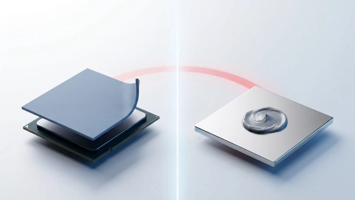
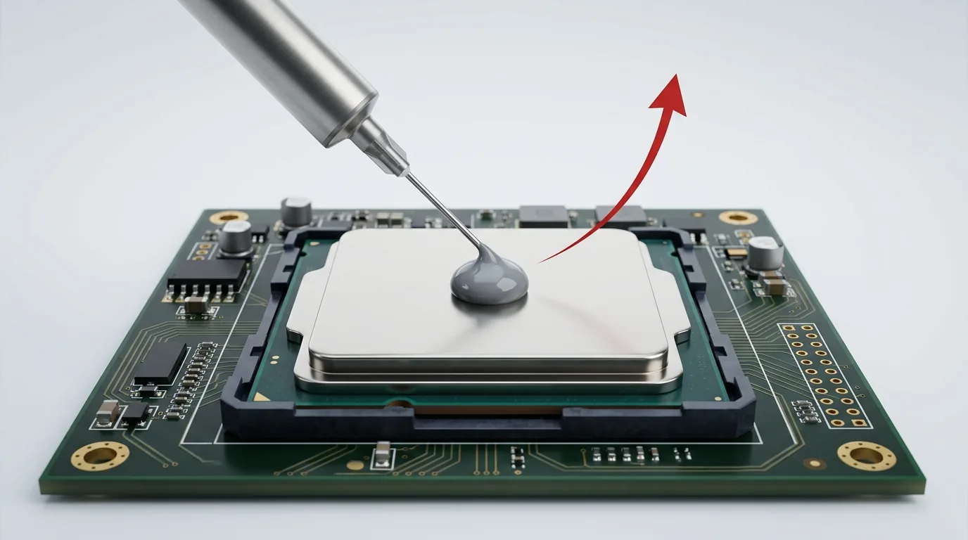
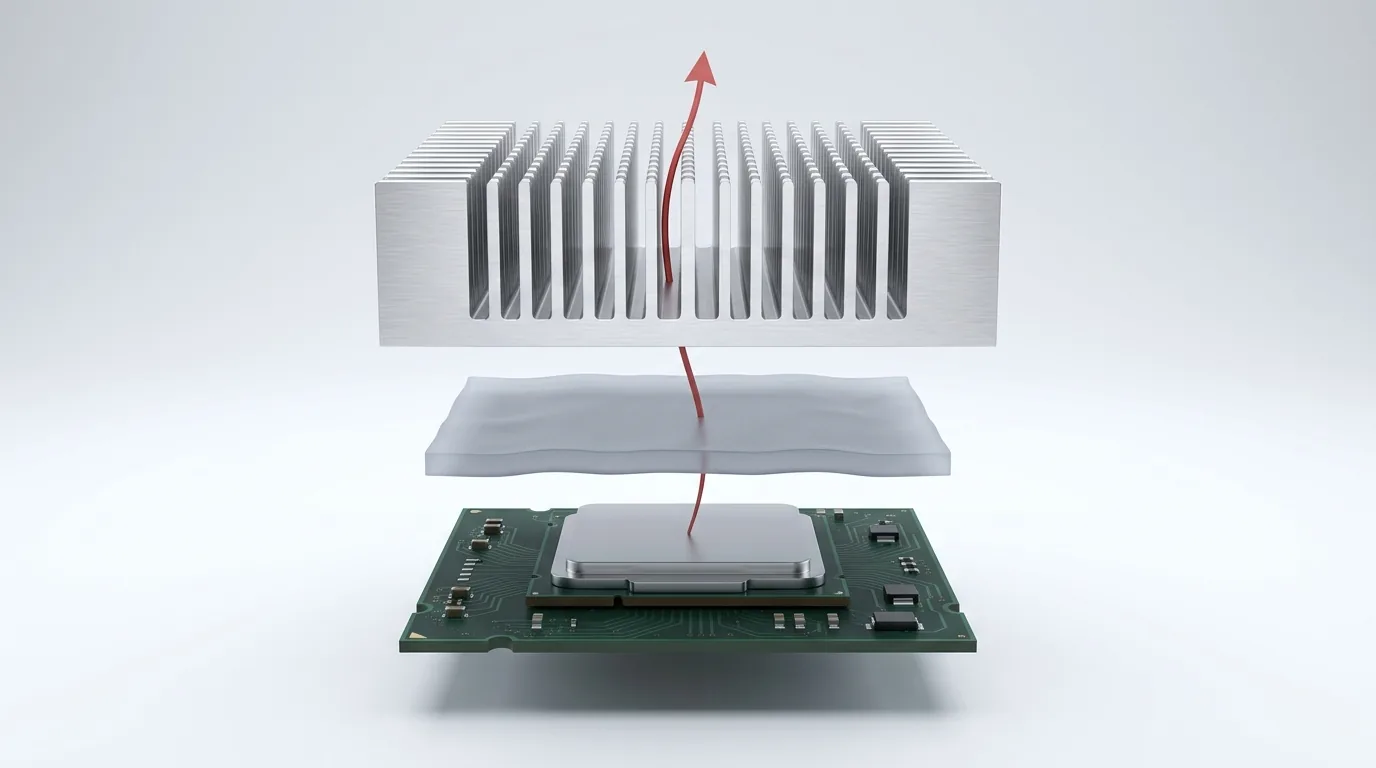
Thermal Interface Materials: Selection Guide
Thermal interface materials fill microscopic air gaps between a chip and heatsink to cut thermal resistance. Compare TIM types, W/mK and how to choose one.
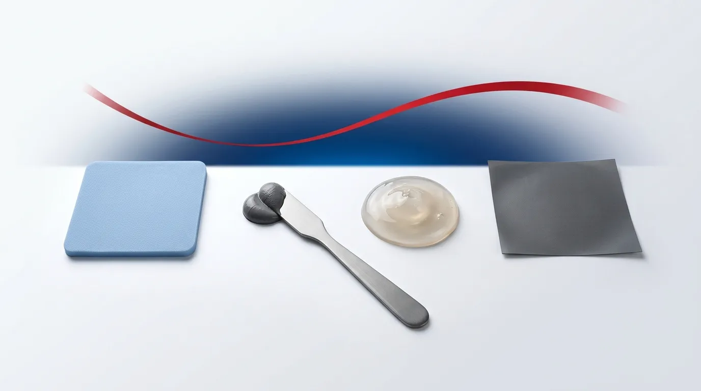
A thermal interface material (TIM) is a thermally conductive medium placed between a heat source — a CPU, GPU, power transistor, or battery cell — and a heatsink or cold plate to displace the air trapped in the microscopic gap between them and lower the thermal resistance of that joint. Get the TIM right and a device runs cooler, throttles less, and lasts longer. Get it wrong and you build a thermal bottleneck no heatsink can fix.
This guide is the map for that decision. It covers every major TIM class, the properties that actually matter when you compare datasheets, a full side-by-side comparison table, a decision framework you can apply to your own design, and application-by-application recommendations. It is written for design, thermal, and sourcing engineers specifying materials into real products — but the physics section is useful to anyone who has ever asked why the paste matters.
ZIITEK has manufactured thermal-management materials since 2006 and ships gap pads, gels, greases, phase-change materials, and carbon-fiber pads to OEMs across EV, datacenter, telecom, LED, and industrial markets. The recommendations below reflect what we see specified at volume, not marketing copy.
Why you need a thermal interface material at all
Two solid surfaces that look flat to the eye are, at the microscopic scale, rough. When you clamp a heatsink onto a chip lid, they touch only at a scatter of high points — real metal-to-metal contact is typically a few percent of the nominal area. Everything in between is air, and air is a thermal insulator (roughly 0.026 W/mK). That trapped air is the reason a bare, unmated joint runs so hot.
A thermal interface material fixes this by flowing into the valleys and squeezing the air out, replacing an insulating gap with a continuous conductive path. The TIM itself is far less conductive than the copper or aluminum it connects — but it is dramatically better than the air it displaces, and that is the whole point. The goal is never “maximum conductivity”; it is the lowest total thermal resistance across the joint at the pressure, gap, and reliability constraints your product actually has.
How thermal interface materials work: conductivity vs. resistance
Two numbers dominate every TIM datasheet, and confusing them is the most common selection error.
- Thermal conductivity (k), measured in W/mK, is a bulk material property. Thermal conductivity tells you how well the material itself moves heat, independent of how thick it is or how hard you press it.
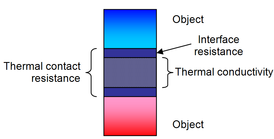
- Thermal resistance / thermal impedance, measured in °C·cm²/W or °C·in²/W, is what the joint actually delivers. It bundles the material’s conductivity, its final compressed thickness (the bond line thickness, or BLT), and the two contact resistances where the TIM meets each surface.
A thicker bond line or poor wet-out can make a high-W/mK material perform worse in-situ than a lower-W/mK material that compresses thin and contacts well. Standardized measurement matters here: the industry reference method is ASTM D5470, which measures thermal impedance across a defined stack so numbers are comparable between vendors. Always compare TIMs on impedance at a stated pressure and BLT, not on headline W/mK alone. If this distinction is new to you, read our deep dive on thermal resistance vs. thermal impedance and the companion guide to understanding thermal conductivity (W/mK) in TIMs.
The physics is Fourier’s law of conduction: thermal resistance rises with thickness and falls with area and conductivity. Practical consequence: thin, well-wetted, low-modulus materials usually win.
The main types of thermal interface materials
TIMs are not one product — they are a family of formats, each solving a different mechanical problem. Here are the classes you will actually choose between.
Thermal grease / paste
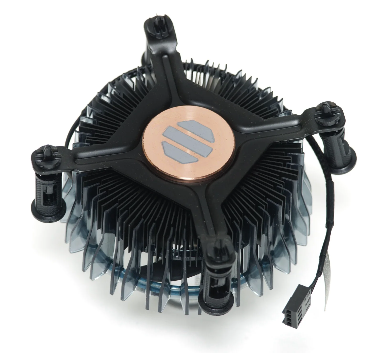
Dispensable, silicone or non-silicone pastes filled with conductive particles. Thermal grease gives the thinnest bond lines and lowest joint resistance on flat, high-pressure interfaces like a CPU lid to a heatsink, which is why it dominates PC and server builds. The trade-off is application skill and long-term reliability (pump-out, dry-out). ZIITEK’s TIG®780 grease line runs 1.0–5.2 W/mK. See what is thermal paste, how to apply thermal paste correctly, and how much thermal paste to use.
Thermal gap pad
Pre-cured, solid, elastomeric pads cut to shape. Gap pads are the workhorse of multi-component boards: they absorb tolerance stack-up, bridge uneven gaps (typically 0.5–5 mm), and provide electrical isolation, all with zero dispensing mess. They need real clamping pressure and are less thermally efficient than grease at the same thickness. ZIITEK’s TIF® pads span 1.25–18 W/mK. For sizing, see what is a thermal pad and the thermal pad thickness & compression guide.
Thermal gel / gap filler
Dispensable, one- or two-component pastes that cure (or stay soft) after application. Gels combine the low assembly stress of a pad with the conformability of grease, filling large or irregular gaps with almost no force on delicate boards — ideal for automated, high-volume lines. ZIITEK’s TIF® gel covers 1.5–9.0 W/mK. Compare formats in gap filler vs. gap pad vs. phase change.
Phase change material (PCM)
Solid at room temperature, PCMs soften at a set transition point (typically 50–60 °C) and flow to a very thin bond line, then re-solidify — combining grease-like performance with pad-like handling and excellent pump-out resistance under thermal cycling. Phase-change materials shine in high-cycle, high-reliability sockets. ZIITEK’s TIC®800 PCM runs 0.95–9.6 W/mK. See what is phase change material (PCM) TIM.
Carbon-fiber / graphite pads
Anisotropic pads with oriented carbon fiber deliver very high through-plane conductivity (9–35 W/mK for ZIITEK’s TIR®700) at low thickness and low pressure — a strong choice where you need high performance but cannot apply much clamping force.
Liquid metal
Gallium-based alloys reach 35–58 W/mK, the highest of any TIM, for extreme heat flux. They demand electrical isolation and corrosion control (they attack aluminum), so they are a specialist, not a default, choice.
Thermal tape / adhesive
Double-sided thermally conductive tapes (ZIITEK TIA®600/800, 0.8–1.6 W/mK) bond and conduct at once, removing clips and screws — lower performance, but unbeatable for mechanical simplicity in LED and low-power assemblies.
Thermally conductive insulators
Where the TIM must also block high voltage, insulating pads (ZIITEK TIS®, 1500–6000 VAC, 1.0–1.6 W/mK) trade some conductivity for dielectric strength.
A recurring decision — a solid pad versus a dispensed paste — comes up so often it has its own guide: thermal pad vs. thermal paste.
Thermal interface materials compared
The table below is the fast way to narrow the field. W/mK ranges reflect commercially available ZIITEK products; your shortlist will vary by supplier.
| TIM type | Typical W/mK | Form | Gap range | Assembly stress | Reworkable | Best for |
|---|---|---|---|---|---|---|
| Thermal grease / paste | 1.0–5.2 | Dispensed paste | < 0.1 mm | Needs pressure | Yes | Flat, high-pressure CPU/GPU joints |
| Thermal gap pad | 1.25–18 | Pre-cut solid | 0.5–5 mm | High (needs clamp) | Yes | Multi-part boards, tolerance take-up, isolation |
| Thermal gel / gap filler | 1.5–9.0 | Dispensed, cures | Any, incl. large | Very low | Limited | Automated lines, delicate boards, odd gaps |
| Phase change (PCM) | 0.95–9.6 | Pad, melts in use | Thin | Moderate | Yes | High-cycle, high-reliability sockets |
| Carbon-fiber pad | 9–35 | Pre-cut solid | Thin | Low | Yes | High performance at low pressure |
| Liquid metal | 35–58 | Liquid | Very thin | Needs pressure | Difficult | Extreme heat flux (specialist) |
| Thermal tape / adhesive | 0.8–1.6 | Double-sided tape | Thin | N/A (bonds) | No | LED, low-power, clip-free assembly |
| Insulating pad | 1.0–1.6 | Pre-cut solid | 0.2–2 mm | High | Yes | High-voltage isolation + conduction |
Format and conductivity narrow the field, but they rarely settle it. The properties below decide the winner — and they are the ones most vendor comparison pages leave out. Ranges here are typical for the material class across the industry, not ZIITEK datasheet values (except where a ZIITEK series is named); always confirm against the specific datasheet at your own pressure and bond line.
| TIM type | Typical impedance (°C·cm²/W) | Hardness | Electrical behavior | Typical temp range | Relative cost |
|---|---|---|---|---|---|
| Thermal grease / paste | 0.02–0.15 | n/a (paste) | Insulating unless metal-filled | −40 to 200 °C | Low |
| Thermal gap pad | 0.5–3.0 | Shore 00 15–70 | Insulating; dielectric-rated grades available | −45 to 200 °C | Low–medium |
| Thermal gel / gap filler | 0.3–1.5 | Shore 00 25–70 (cured) | Insulating | −45 to 200 °C | Medium |
| Phase change (PCM) | 0.05–0.3 | Solid; softens at 50–60 °C | Insulating | −40 to 150 °C | Medium |
| Carbon-fiber pad | 0.05–0.5 | Shore 00 40–70 | Often electrically conductive | −40 to 200 °C | High |
| Liquid metal | 0.005–0.02 | Liquid | Conductive — must be isolated | −10 to 200 °C | High |
| Thermal tape / adhesive | 1.0–5.0 | n/a (bonds) | Insulating | −40 to 150 °C | Low |
| Insulating pad | 1.0–3.0 | Shore A 40–80 | Insulating, 1500–6000 VAC (ZIITEK TIS®) | −45 to 200 °C | Low–medium |
Read the two tables together. A carbon-fiber pad and a gap pad look one generation apart on W/mK, but the carbon-fiber pad’s electrical conductivity disqualifies it wherever the gap pad’s dielectric rating was the reason you chose a pad at all. Liquid metal wins every impedance row and still loses most designs on isolation and corrosion.
The properties that actually matter
Once you know the format, these are the datasheet lines that decide the winner:
- Thermal conductivity (W/mK) — the headline, but only meaningful alongside thickness and pressure.
- Thermal impedance (°C·cm²/W) — the real-world number; lower is better. Compare at a stated pressure per ASTM D5470.
- Bond line thickness (BLT) — thinner is better for resistance; the material must still fill your worst-case gap.
- Hardness (Shore 00 / A) — softer pads conform better and need less force but can flow or tear; harder pads survive handling.
- Compression / deflection vs. pressure — how much a pad thins under load, and how much force that costs your fasteners and PCB.
- Dielectric strength (VAC) and volume resistivity — mandatory when the TIM sits across a voltage.
- Operating temperature range — ZIITEK materials typically run −45 to 200 °C; confirm against your hotspot and ambient.
- Viscosity and cure (for dispensables) — governs dispense speed, sag, and line throughput.
- Outgassing / silicone content — critical for optics, sensors, and sealed enclosures where silicone contamination is a defect.
Narrowing the field: a five-question triage
You do not pick a TIM from a W/mK ranking — you match it to five constraints. Walk them in order:
- How big and how variable is the gap? Sub-0.1 mm flat joint → grease, PCM, or liquid metal. 0.5–5 mm with tolerance stack-up → gap pad or gel. Large or irregular → dispensed gel.
- How much clamping pressure can the assembly take? Delicate boards or large ICs that crack under load → low-stress gel or soft pad. Rigid, well-fastened joints → grease or firm pad.
- How much heat, over how small an area (power density)? Higher flux pushes you up the conductivity ladder — from standard pads toward high-W/mK carbon-fiber pads or liquid metal.
- Does the joint need electrical isolation? If yes, an insulating pad or a dielectric-rated gap pad; never a bare conductive grease or liquid metal.
- Rework, reliability, and volume. Field-serviceable? Keep it reworkable (grease, PCM, pad). High thermal cycling? Favor PCM or a stable pad over grease that can pump out. High-volume automated line? A dispensed gel usually wins on throughput.
Answering these five in sequence usually leaves one or two viable classes. For a worked, criteria-by-criteria walkthrough, see how to choose a thermal interface material.
Application-by-application selection
Different products stress TIMs differently. Typical starting points:
- CPU / GPU and servers / datacenter. Flat lids, high pressure, high flux, and rework needs favor high-performance grease or PCM; PCM’s pump-out resistance is attractive for always-on datacenter duty.
- EV battery packs and energy storage (ESS). Large, uneven gaps between cells/modules and cold plates, minimal assembly stress, plus electrical isolation → dispensed gap filler / gel and insulating pads dominate.
- Power electronics / inverters. High flux plus high-voltage isolation → dielectric-rated gap pads or insulating pads.
- 5G / telecom radios. Many small components, tolerance stack-up, sealed outdoor enclosures → gap pads and low-outgassing gels.
- LED lighting. Cost- and simplicity-driven, modest flux → thermal tape or thin pads.
- Industrial, automotive, and medical. Wide temperature range, long service life, and standards compliance push toward stable pads/PCM with documented certifications.
Reliability: how TIMs fail (and how to avoid it)
A TIM that works on day one can still fail over years. The failure modes to design against:
- Pump-out — thermal cycling slowly squeezes grease out of the joint. Mitigate with PCM or a stable pad.
- Dry-out / bleed — the oil carrier in some greases migrates away, leaving dry filler. Choose stable formulations for long-life products.
- Thermal cycling fatigue — repeated expansion/contraction degrades the bond line; match the TIM’s modulus to the joint.
- Outgassing — volatile silicones condense on nearby optics and contacts; use low-outgassing or silicone-free grades near sensitive surfaces.
When a joint must be serviced or a TIM replaced, clean removal matters — see how to remove and clean off thermal paste.
Format, manufacturability, and volume
At production scale, how a TIM is applied is as important as its conductivity:
- Die-cut pads — fast to place, consistent, but generate material waste and tooling cost.
- Dispensed gels/greases — automatable, near-zero waste, ideal for high mix and large or variable gaps.
- Screen / stencil printed — thin, uniform layers for high-volume flat parts.
- Form-in-place — robot-dispensed gaskets/fills for complex geometries.
Sourcing engineers should weigh throughput, scrap, tooling, and rework alongside the thermal number — the cheapest datasheet is not always the cheapest installed joint.
Compliance and certifications
For products that ship into regulated markets, the TIM’s paperwork is part of the spec:
- Flame rating — UL 94 V-0 is the common requirement; ZIITEK materials carry UL Yellow Card recognition.
- Environmental — RoHS and REACH compliance for electronics sold into the EU, plus California Prop 65 for the US.
- Quality systems — IATF 16949 (automotive), ISO 9001, and ISO 14001 signal a supplier that can hold tolerances at volume.
- Silicone-free options — where silicone outgassing is unacceptable, non-silicone pads (ZIITEK Z-Paster®100) meet the thermal need without the contamination risk.
Frequently asked questions
What are examples of thermal interface materials? Thermal grease/paste, gap pads, gap fillers/gels, phase change materials, carbon-fiber and graphite pads, liquid metal, thermally conductive tape, and insulating pads.
What is the best thermal interface material? There is no single best — it depends on your gap size, pressure budget, power density, isolation needs, and reliability requirements. Grease gives the lowest resistance on flat high-pressure joints; gap pads and gels win on multi-component boards and low-stress assembly; PCM wins on high-cycle reliability.
How is TIM performance measured? By thermal impedance (°C·cm²/W) across a defined stack, typically per ASTM D5470, at a stated pressure and bond line thickness — not by W/mK alone.
Do thermal interface materials conduct electricity? Some do (liquid metal, some greases and pads); many are formulated as electrical insulators with rated dielectric strength. Always check volume resistivity and dielectric rating when the TIM sits across a voltage.
Choosing with confidence
The right thermal interface material is the one whose format, conductivity, mechanical stress, and compliance all match your joint — found by working the five-question framework above, then comparing candidates on impedance at your real pressure and gap, not on headline W/mK. Start from the application table, narrow to one or two classes, and validate on your own hardware.
ZIITEK engineers TIMs across every class in this guide and supports OEM designs from prototype to volume. If you are specifying a material, request samples, a datasheet, or engineering support for your design and we will help you match the material to your thermal, mechanical, and compliance targets.