Custom Die-Cut TIM Parts: A Capability Checklist
A custom die-cut TIM part is a stack, not an outline. Seven questions — material, tolerance, format, operations, tooling, delivery, quality — set feasibility.
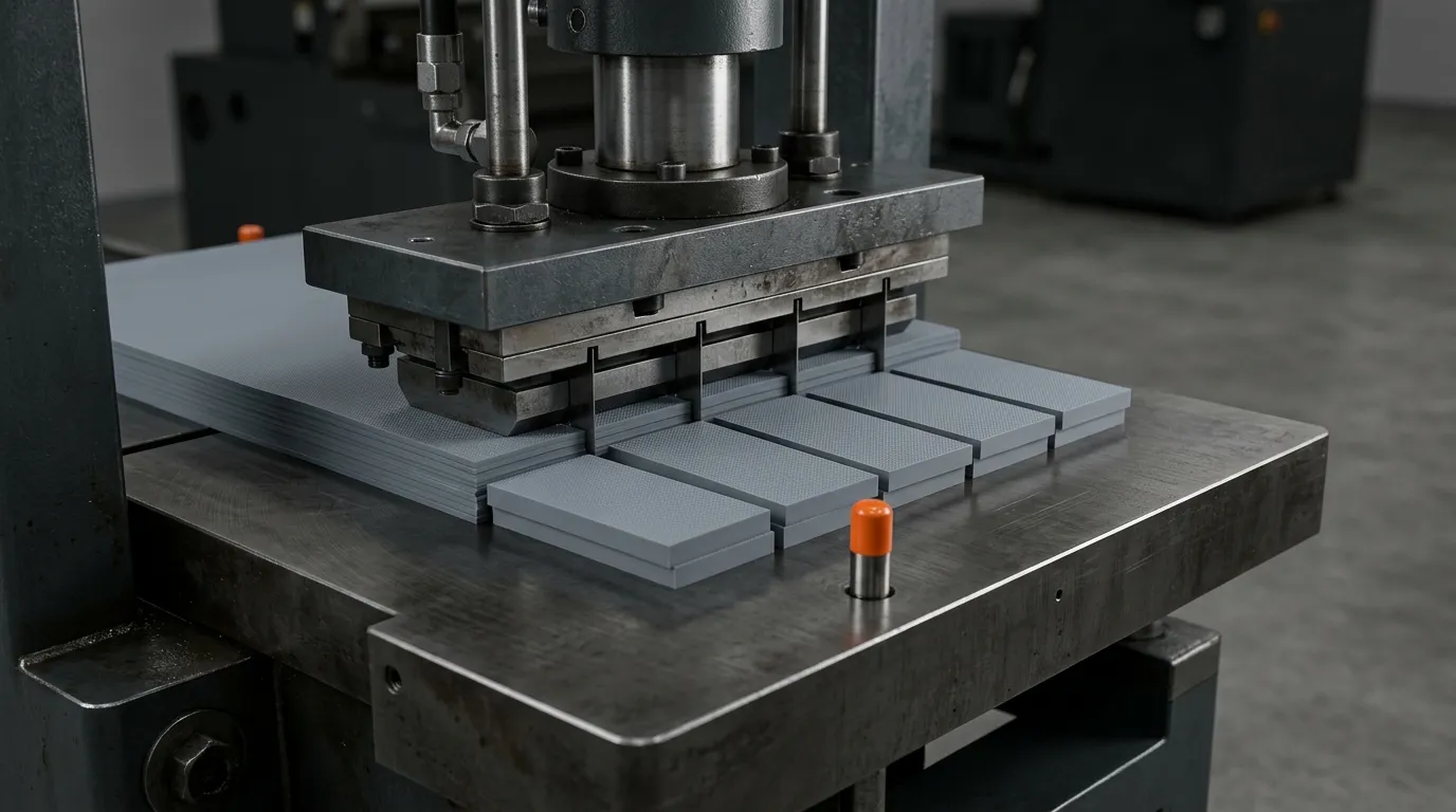
Three quotes land for the same drawing and sit within 30% of each other. The line items match: same 3 W/mK pad, same 2.0 mm thickness, same tolerance row copied from the same template. Whatever separates them is not in the line items — it is in the process envelope behind them.
That envelope is what each shop's process can hold once the job leaves the sample bench. Custom die-cut TIM parts (thermal interface material parts) are cut, not molded, so the capability looks flat from the outside — a die, a press, a sheet. The reality is a set of bounded ranges stacked on top of each other, and the narrowest one decides whether your part is buildable. What follows is a buyer's checklist for those ranges: one question per axis, what a real answer contains, and what should take a supplier off your shortlist.
Custom Die-Cut TIM Parts Are a Stack, Not a Shape
The die does not cut a shape out of a material. It shears through a laminate, and every layer in that laminate behaves differently under the blade.
A typical construction has four: the functional TIM layer that carries the heat, a pressure-sensitive adhesive that holds the part in place, a carrier film or fiberglass scrim that keeps a soft pad from stretching, and a release liner that lets the whole thing travel on a roll. The cut has to sever some of those layers and stop inside another. That single requirement — where the blade stops — is the difference between kiss cutting and through cutting, and it drives the tooling, the feed, and the format your assembly line receives.
Three consequences follow, and all three belong in the capability conversation rather than in the drawing.
Registration is a capability. Each added layer needs to land inside the previous one, and the error accumulates across the stack. A converter who cuts single sheets well may still print a stack whose adhesive window sits outside the pad outline on one edge. Ask what registration tolerance they hold on a four-layer build, not whether they can laminate.
The cut edge is part of the thermal path. A crush-cut edge leaves a slightly denser, sometimes concave band of material along the perimeter, and on a small part that band is a meaningful share of the contact area. On thin pads it also curls. The edge is not cosmetic, so the acceptance criterion has to name it.
The stack has a thickness tolerance before anyone cuts it. Pad plus adhesive plus carrier adds up, and buyers routinely calculate the gap from the pad nominal alone. If the drawing says 2.0 mm and the assembly adds a 0.05 mm adhesive layer, the part that arrives is not the part the thermal model assumed. What a thermal pad is covers the material side of that gap; the stack arithmetic is the converter's side.
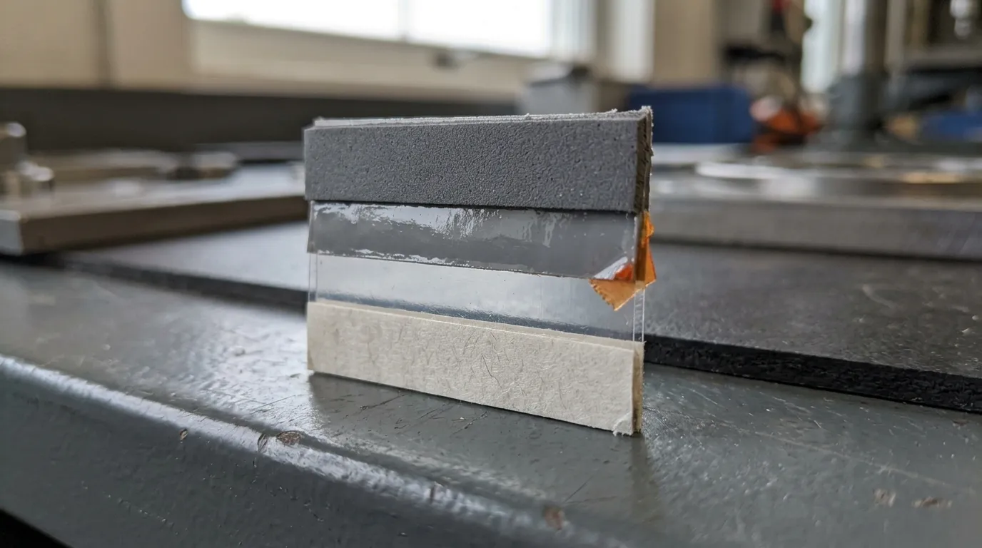
Four layers, one cut: pad, adhesive, carrier film and release liner, each one adding its own thickness to the stack the assembly actually sees.
Step 1: Confirm the Material Envelope, Family by Family
The first question that separates a real answer from a brochure is narrow on purpose:
Which of these families do you cut in-house, and what is the thickness range for each one?
A single range across all families — "0.1 mm to 10 mm" — is the red flag. It describes the widest thing the shop has ever cut, not what it can cut in the grade you need. Soft silicone at 5 mm and a 0.127 mm phase-change film are not the same operation: one needs depth and clean release from a deep cavity, the other needs a blade that will not deflect on a film thinner than a business card, and both need a liner that survives the strike.
A capability table that answers the question properly is per-family, and it is short enough to fit on one page:
| Family | Typical thickness range | What else the buyer needs from that row |
|---|---|---|
| Silicone gap pad, 1.0–16.0 W/m·K | 0.25–5.0 mm, UL 94 V-0 | Hardness band available at your thickness |
| Low-volatile silicone pad, 1.5–6.0 W/mK | 0.25–5.0 mm | Outgassing data for optical assemblies |
| Non-silicone pad, 1.5–10 W/mK | 0.25–5.0 mm | Whether adhesive is silicone-based (it often is) |
| Thermally conductive insulator | 0.13–0.5 mm, withstand voltage 1,500–6,000 VAC; dielectric strength up to 6 kV/mm | Which of the two the datasheet quotes, and at what thickness |
| Graphite heat spreader | 0.012–0.50 mm | In-plane vs through-plane direction of the cut |
| Phase-change material | 0.127–0.508 mm | Whether the die can cut the carrier tab without cracking it |
| Silicone foam seal, 20–110 kPa at 25% compression | Thickness per grade; foam stock runs thicker than pad stock | Compression set and any IP rating with its test condition |
Those ranges are ZIITEK's own, and they are family bands rather than per-grade figures — where a grade datasheet is narrower than the band, the datasheet governs. The point of showing them is not that they are the widest in the industry — it is that they are stated per family, with the secondary property a buyer actually needs, which is what you should demand from every quote you compare against them.
Two boundary rules matter more than any single number:
- Below roughly 0.25 mm in a soft elastomer, the stock is usually skived before it is cut. The sheet has to be shaved to a uniform gauge from a block first, which is a different machine and a different tolerance chain; skiving thin stock to gauge sits upstream of the die. If your drawing calls for 0.15 mm silicone, ask whether the converter skives in-house or buys skived sheet, because that answer changes both lead time and thickness control.
- A foam that also seals is two specifications, not one. Compressive stress at your working deflection is the sealing number; thermal conductivity is irrelevant at 0.06 W/mK. If the part carries an IP rating, the rating only means something with the immersion condition stated — IEC 60529 defines IP68 as dust-tight plus protection against continuous immersion, with the conditions agreed between manufacturer and user.
Step 2: Demand Four Tolerance Statements, Each With Its Method
Die cutting is a profile process, so tolerance never reduces to one line. Why it scales with material thickness and feature size, and why a serious converter quotes it per feature rather than per part, is set out in how to specify a die-cut thermal pad. What this step adds is the verification side: four statements to demand, and the method each one has to name.
Ask for four separate statements:
- Outline tolerance on the outer profile, at your material thickness.
- Positional tolerance on holes, slots and windows relative to a stated datum — not to the nearest edge.
- Thickness tolerance, with the gauge pressure at which thickness is measured, because soft pads are compressible and two labs will disagree about the same part if the method is not fixed.
- Edge acceptance, as a written criterion: burr height, concavity, and whether a scuff on the release liner is a reject.
The mechanics behind the numbers are worth knowing, because they tell you which tolerance will bite first:
- Soft material deflects before it separates. The blade compresses the sheet, then shears it, so the cut edge comes out slightly concave and the effect grows with stock thickness. On a seal that is acceptable; on a visible trim part it is not.
- A hole smaller than the material thickness is generally unreliable. The blade has to punch through the full stack and small holes in thick stock distort. Where that limit sits depends on the grade and the die, so the useful question is "what is the smallest reliable hole in this material", not "what is your minimum hole".
- Narrow flanges lose tolerance first. A wall narrower than the material thickness has nothing to support it and tends to come out wavy.
- Thickness outranks X-Y for a thermal part. A 0.2 mm shift in outline rarely changes a junction temperature. A 0.2 mm error in thickness changes the pressure, and pressure changes the result. If a supplier quotes ±0.1 mm on everything and cannot say whether that applies to thickness at your compression, the number is decoration.
One boundary is worth stating here, because it decides whether this axis is even the right one: it assumes a fixed-thickness part. Where the gap varies widely across a board, the answer is usually a dispensed gap filler rather than a pad cut to a tighter tolerance — no die holds a bond line that changes by a millimetre across an assembly.
This is where the buying decision usually goes wrong: the drawing is treated as the specification, when the drawing only describes geometry. The six items that belong on the drawing and the RFQ — function, material and compliance, thickness and compression, geometry rules, supply format, volume — are worked through in that spec article. What a capability review adds is the other direction: whether the shop can hold the numbers you just wrote, and what evidence it has that it can.
A converter that runs die-cutting and converting capability as a production cell rather than a service bureau will normally answer with measured capability from a first article, not with a tolerance table. That distinction is the whole test.
Step 3: Fix the Supply Format Before the Drawing Freezes
Supply format is decided at the cutting stage and paid for on the assembly line, and it is the item most often left off a quote. The four formats below are four different answers to one question — where the blade stops, and what carries the part from there — and the part itself is identical in all of them while the labour around it is not. That is where most custom die cut thermal pads quietly become expensive.
| Format | What arrives | Where it wins | Where it costs |
|---|---|---|---|
| Through cut, loose parts | Bagged or trayed parts | Simple builds, hand placement, low volume | One manual pick per part; loose parts need orientation |
| Kiss cut on liner | Parts on a continuous liner, adhesive live | Operator peels and places in one motion; no fixture | Liner has to suit the peel angle and the part size |
| Part-on-roll / tape and reel | Indexed pockets or liner with registration | Automated feeders, high-volume lines | Tooling for the carrier; feeder must match pitch |
| Sheeted stock | Sheets of parts | Flat, large parts; secondary forming | Cutting the sheet into parts on the line |
The format also changes how the part is cut. A soft release liner absorbs part of the shear force instead of transmitting it into the pad, so cut consistency drops; a fiberglass scrim does the opposite and resists shearing, which calls for more tonnage and tighter die clearance. Both are solvable, but only if the format is known before the die is ordered. Freeze the drawing first and the format second, and you will usually pay for the liner twice — once in tooling, once in a rejected first article.
Ask two questions here. Which format does the quote assume? And what does the converter need from you about the feeder, the peel angle and the maximum roll diameter? A supplier who answers "we can do any format" without asking about your line has answered a different question. The compression behaviour that decides whether a peeled part seats correctly is covered in thickness and compression behaviour.
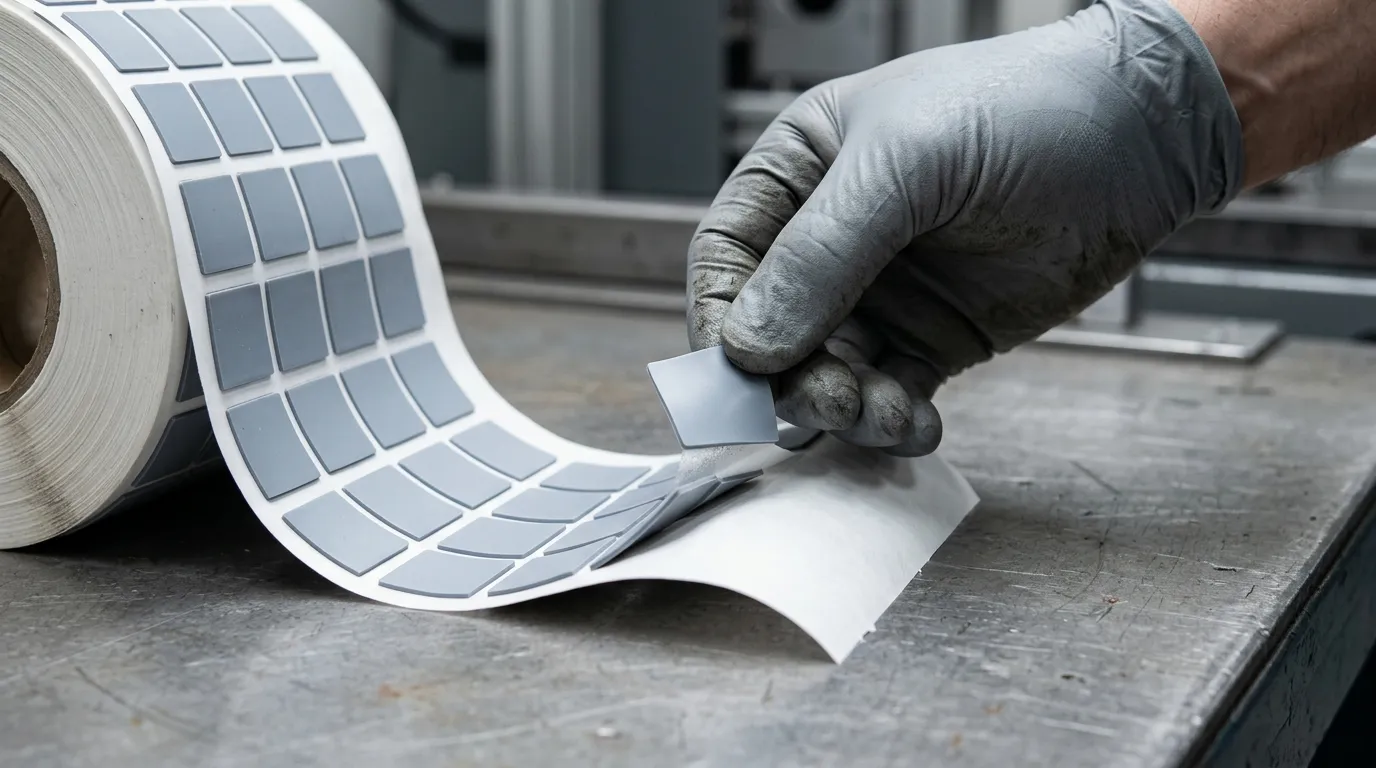
Kiss cut on liner: the blade stops inside the liner so the parts stay indexed — the format decision that removes a manual placement step from the line.
Step 4: Count the Operations Around the Cut
Almost no die cut thermal pad is only a cut. The capability that matters is the line, not the press, and the way to test it is to ask for the operation list.
Take a realistic build: a 1.0 mm silicone pad, an adhesive on one face, a 0.05 mm PET carrier on the other, and a release liner — delivered kiss cut on a roll, in a shape that clears two connectors. That part touches slitting, lamination, die cutting, and slitting again. A shop that cuts well but subcontracts lamination has added a handling step, a second thickness tolerance, and a break in traceability between the material lot and the finished part.
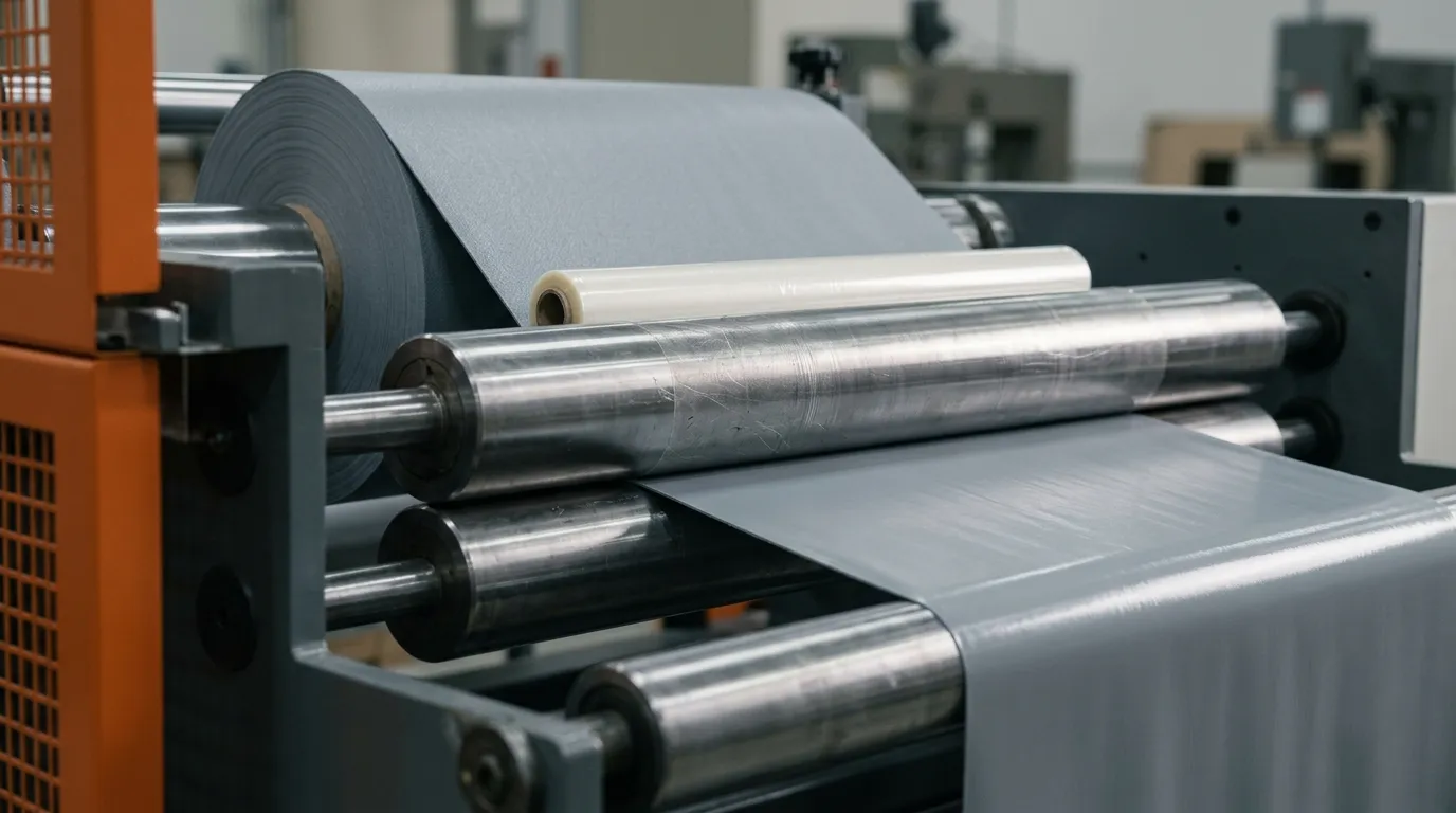
Lamination happens upstream of the die: the adhesive and carrier are joined on the line, and their thickness tolerance rides into the finished part.
Three questions get at this quickly:
- Which steps run in-house, and which are subcontracted? Subcontracting is not disqualifying; not saying so is.
- How is registration held on a multi-layer build? Ask for the cumulative tolerance across the stack, not the per-layer figure.
- What happens to the material between steps? Silicone picks up dust and handling marks, adhesive picks up liner residue, and a pad that sat compressed on a roll can arrive with a set.
Alternative processes belong here as well, as a boundary rather than a comparison. Laser cutting chars and gums silicone; knife cutting drags and stretches soft pads; waterjet gives a clean edge but is slow and expensive per part. Those routes make sense for prototypes, for rigid or thin stock, and for geometry a blade cannot reach — not for production volumes of soft thermal pads. A converter who offers them is telling you where their die envelope ends.
Step 5: Match Volume to the Tooling Class
Tooling class is where most of a 30% spread comes from, and it is the axis buyers question least. Thermal pad die cutting runs in four classes, and each has a volume band it serves.
| Class | Made from | Volume band it serves | What to ask |
|---|---|---|---|
| Tooling-free cut | Plotter, knife or waterjet path | Prototypes, first articles, design still moving | What is the cost per iteration? |
| Steel rule die | Blade bent into a laser-cut board | Short to mid-volume production, sheet stock | Die life in strokes; who owns the die |
| Rotary die | Same blade on a cylinder, roll stock | High volume, continuous | Web width and registration capability |
| Matched metal / solid die | Machined steel | Tight tolerance, long runs, abrasive filled grades | Clearance for your filler loading |
The die itself is a one-time cost per revision, not per order, and it is reusable for the life of the program. That is why the fair comparison is at your annual quantity, not at prototype quantity — and why a quote that includes tooling without naming the die class is not comparable to one that does.
Tooling is bought per revision, not per order. Ask what revision C will cost before you approve revision A — that answer tells you how the supplier treats your design cycle.
Two clauses are worth reading twice. Die ownership: if the tool is not yours or not transferable, you are locked in for the life of the part. Revision handling: when the drawing changes at revision C, does the existing die get modified, retired, or re-quoted? A shop that treats a die as a consumable will quote a new one at every change; a shop that owns its tool room will usually tell you what the modification costs before you commit.
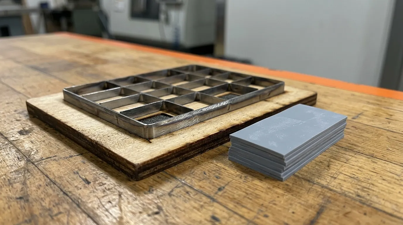
Steel rule die and its output: the tooling class, not the press, sets the per-piece price and the tolerance the part can hold.
Step 6: Ask for the Quality Documents and the Inspection Method
Certificates are a starting point, not an answer. IATF 16949, ISO 9001, ISO 14001 and QC 080000 tell you that a system exists; they do not tell you what happens to your lot on a Thursday afternoon. What separates converters at this stage is whether the measurement loop is defined.
The documents to request, in the order that reveals the most:
- First article inspection (FAI) report for the actual part, with the features measured, the instrument used, and the values against the drawing — not a generic capability sheet. If the program is automotive, ask which PPAP level they submit and who signs it.
- Process capability on thickness, expressed as Cpk at your nominal, if the part is going into an automotive or medical program. A Cpk number is the difference between "we hold ±0.1 mm" and "we hold it on 99.7% of parts".
- Sampling plan — the AQL and the inspection level, so you know what "inspection" means at the receiving end.
- Traceability: is there a lot code on the part or its bag that maps back to a material lot and a run date? Without it, a field failure cannot be traced to a batch.
- First-article and production timing, quoted separately: how long the first article takes from an approved drawing, and what MOQ applies to the format you asked for. A new die, a revision and a repeat order move both numbers, so a single lead time with no reference point is not an answer.
- Cut-edge criterion, with the method (visual comparator, magnification, profile measurement) and the accept/reject boundary.
- Flame and material compliance evidence for the grade you are buying — a UL yellow card covering the specific compound, and RoHS/REACH declarations. UL 94 ratings apply to a tested configuration, so a V-0 claim on a resin is not automatically a V-0 part in 0.5 mm.
One item is routinely skipped and matters most for a thermal part: re-measuring thermal performance after cutting. The die changes the edge, the adhesive changes the bond line, and handling changes the surface. A die cut thermal interface material part that measured a given impedance as molded sheet can measure differently once it is a cut part at your assembly pressure. Ask whether the converter re-tests impedance on the finished part at a stated pressure and bond line thickness — the method in ASTM D5470 is the usual reference, and it is only comparable when the pressure and thickness are stated alongside the number.
If the program is automotive, the quality-system question has a specific shape; what IATF 16949 means for a TIM buyer covers what the certificate does and does not commit the supplier to.
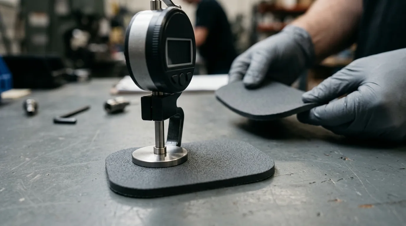
Inspection is a method, not a certificate: thickness at a stated gauge pressure, edge condition, and a lot code that survives to the assembly line.
What a Real Capability Answer Looks Like
Seven questions, one per axis. A supplier who can answer all seven with numbers is telling you something different from one who answers with adjectives — and you can run the same list against every quote in front of you this week.
| Axis | The question to send | A real answer contains | Red flag |
|---|---|---|---|
| Material | Which families do you cut in-house, at what thickness range each? | A per-family table with hardness or withstand voltage | One global range for everything |
| Tolerance | What tolerance do you hold per feature, at my thickness, and how is thickness measured? | Per-feature values, gauge pressure, FAI evidence | A single ± figure with no method |
| Supply format | Which format does the quote assume, and what do you need to know about my feeder? | A named format and liner, plus line questions | "We can do any format" |
| Added operations | Which steps run in-house, and what is the stack registration tolerance? | An operation list with in-house/subcontract marked | Unnamed subcontract steps |
| Tooling | Which die class, what die life, who owns the die, what does a revision cost? | Die class, stroke life, ownership clause | Tooling as a line item with no class |
| Delivery | How long to first article and to production, and what MOQ applies to my format? | Two dates, an MOQ per format, and what changes them | One lead time, no MOQ |
| Quality | FAI, Cpk on thickness, sampling plan, lot traceability, cut-edge criterion | Documents for this part, not a brochure | Certificates only |
The order you ask in matters as much as the list. Buyers typically lead with price and then discover feasibility in the first article — which is the most expensive possible sequence, because a die has already been cut by then. Send the stack drawing, the annual volume and the supply format first, and ask for two things back before price: the material-and-thickness table for your family, and a first article plan. A shop that cannot produce those two documents quickly is not going to produce a controlled part slowly.
ZIITEK runs die-cutting and converting lines for foam, insulation, conductive and tape constructions across four production bases, with quality systems certified to IATF 16949, ISO 9001 and ISO 14001 and a UL yellow card (E331100) that covers named thermal and foam grades rather than whole material families. The families it cuts each have a published range of their own: silicone pads at 1.0–16.0 W/m·K and 0.25–5.0 mm in the thermal pad product range, and non-silicone pads, insulator grades, graphite heat spreaders and phase-change films on their own pages.
Send the stack, not just the outline. Whether a part is feasible is decided by the layer list and the seven numbers above, and a feasibility review on that basis takes one exchange rather than three rounds of first articles.