5G Thermal Management: Base Stations & Optical Modules
5G thermal management starts at the gap, not the W/mK: pick thermal materials for base station radios and optical modules by heat path and mounting pressure.
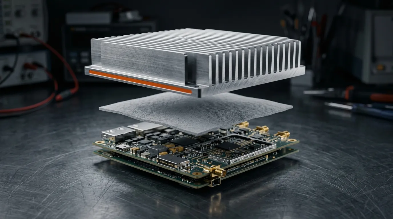
A 5G radio and an optical transceiver usually fail thermally for opposite reasons. The radio has watts to spare but nowhere to put them: a sealed outdoor housing, no fan, and a heat sink that cannot grow because the tower wind load and the installation crew both say no. The optical module has moving air above it and almost no room to use it: a hot DSP pressed against a cage roof, with a clamping force measured in newtons rather than newton-metres.
That mismatch is the whole of 5G thermal management in practice. It is the discipline of holding junction temperature inside its limit by sizing the heat path from the die to the ambient — package, board, thermal interface material, heat sink or enclosure — and it rewards format choices far more than it rewards a higher W/mK number on a datasheet.
Get the format wrong and the failure is not a slightly warmer chip. It is a gap that never closes at the far end of the tolerance stack, a pad that hardens out of contact after 500 thermal cycles, or a silicone residue that condenses on an optical surface inside a sealed module. Most of those problems are decided by three numbers you can measure before you ever open a thermal simulation: the gap, the mounting pressure, and the ambient the part has to survive.
5G Thermal Management Means Two Problems, Not One
Separate the two applications before comparing materials: a pad family that performs well in an antenna unit can be the wrong material inside a transceiver cavity.
The base station radio (RRU or AAU). The power amplifier stage converts DC into RF at maybe 30–45% efficiency, so for every 10 W of RF delivered there is more heat than signal. In a 32- or 64-channel Massive MIMO array those amplifiers multiply; the heat is spread over many small sources on a large board rather than concentrated in one place. Cooling is passive: cast aluminium fins, sometimes heat pipes or a vapour chamber, rejecting to air that can sit near 55 °C on a sunny site. The interface materials sit behind a sealed housing, in a stack that gets compressed by screws and standoffs — the same construction whether the unit is a macro site radio or a pole-mounted small cell, only with less metal to work with in the smaller one.
The optical module. An 800G transceiver puts a DSP and very fast SerDes lanes into a package the size of a chocolate bar. Kilowatts per cubic metre is not a figure of speech here — the power density is an order of magnitude above a server board's average, and it is concentrated under a flat lid that a spring-loaded cage presses against a heat sink. There is no screw torque to rely on, the module must stay hot-swappable, and the cavity around the optics tolerates almost no chemical contamination.
| 5G base station radio (RRU / AAU) | Optical module / transceiver | |
|---|---|---|
| Dominant heat source | Power amplifier stage, plus baseband and power supply | DSP and high-speed serial lanes |
| Power density | High total power, moderate per-component density | Tens of watts under a small flat lid |
| Heat path | Die → board → TIM → heat sink / vapour chamber → enclosure wall → ambient | Die → package lid → TIM → cage → host heat sink |
| Mounting force | Defined by hardware: screws, standoffs, spring clips | Defined by the cage: low, and shared with connector alignment |
| Failure mode to avoid | Contact loss after cycling, compression set, corrosion | Outgassing onto optics, pump-out, insufficient contact force |
Network operators track energy efficiency at site level, and a single radio's power draw is a small line in that budget — but every watt the interface material fails to move shows up twice, once as a hotter junction and once as a shorter service life. The levers in this article are mechanical before they are electrical.
Where the Heat Goes in a 5G Base Station Radio
Follow one power amplifier from junction to sky and the number of interfaces becomes obvious — and so does the fact that the thermal interface material is only one of several resistances competing for the same temperature budget.
The die conducts through its attach layer into the package and then into the board, where thick copper planes or embedded metal spread the heat sideways. From the board, heat crosses the interface material into the heat sink base, travels up the fins by conduction, and leaves them by natural convection to ambient. On a sealed radio the last step is the enclosure wall itself, which is why cast housings double as heat sinks and why a plastic enclosure is a thermal decision rather than a cosmetic one.
Where the fins cannot sit directly over the amplifiers — a narrow pole-mounted unit, for instance — a heat pipe or vapour chamber carries the heat sideways to them first. Neither has moving parts, and that is the point in a sealed housing: there is no clean air path to spare and no service visit to rely on. Liquid cooling moves the same heat at far higher flux, but it needs a pump, plumbing and a coolant loop that a pole-mounted radio has neither the room nor the service access for, which is one reason most AAUs stay passively air-cooled.
Two details in that chain decide most selection outcomes. First, the power amplifier is the hot spot, not the board average: a component that runs 40 °C above the surrounding copper will push its local interface past its design limit long before the enclosure temperature looks alarming. Second, on a Massive MIMO array the same interface is repeated dozens of times; a material that conforms well but needs high pressure to do it will fight the assembly process at every one of those positions. Where a sub-6 GHz array moves into millimetre-wave bands, the elements get smaller and more numerous, and the heat per channel stays similar while the contact area per channel falls — a harder thermal problem in the same mechanical envelope. The radio architecture behind that shift, including Massive MIMO and beamforming, is defined in the 3GPP 5G system overview.
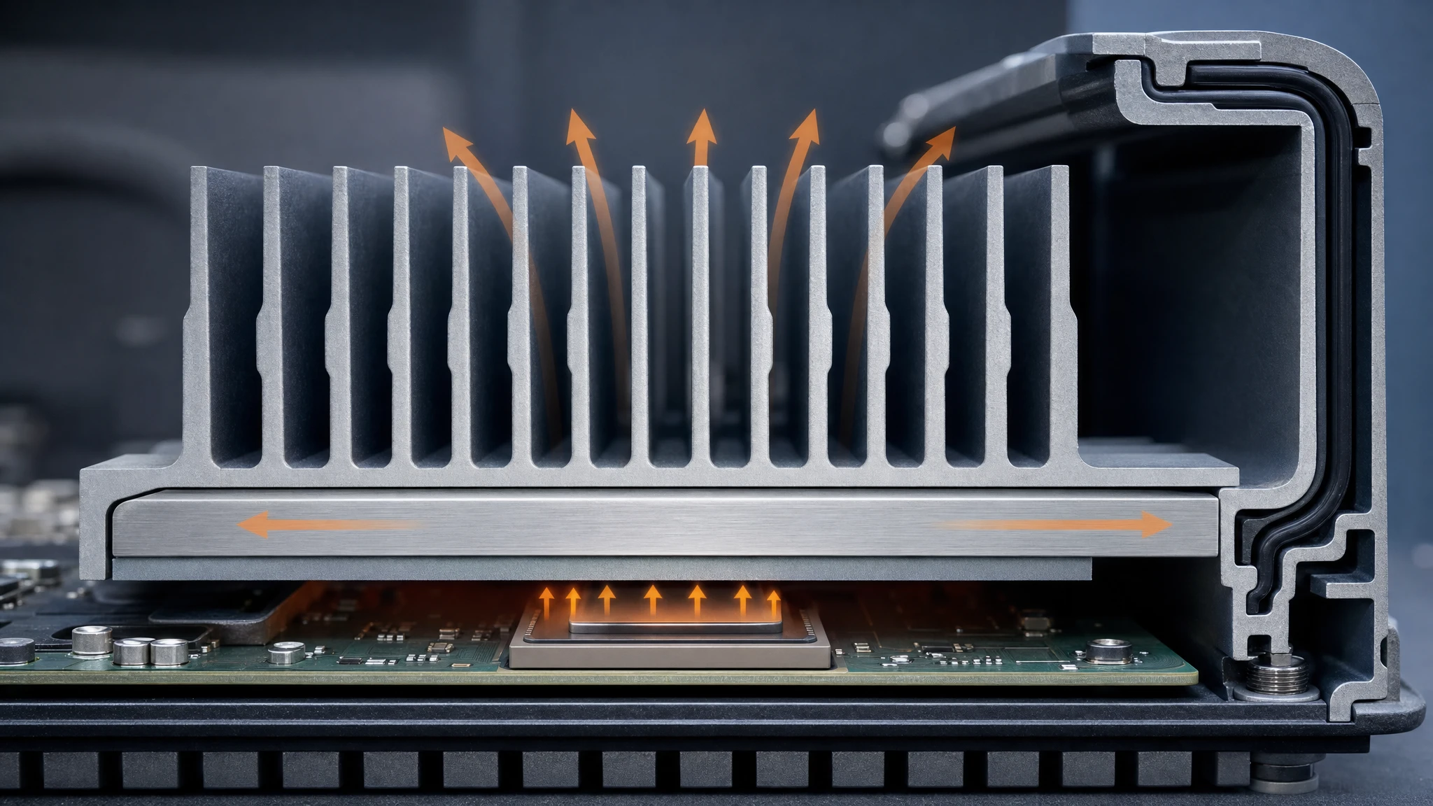
Heat leaves a 5G radio through a chain of five interfaces. The pad between board and heat sink is usually the only one you can still change late in the design.
Published reviews of base station cooling make the same point from the other direction: the thermal load of 5G equipment is a system-level constraint, and small improvements in interface resistance are among the cheapest remaining levers once the heat sink and housing are frozen. A 2025 review of thermal management strategies for 5G and 6G base stations collects those strategies across air cooling, liquid cooling and materials. If you need the vocabulary first, our primer on what W/mK actually tells you covers how the headline number relates to real interface resistance.
Inside an Optical Module: the Tightest Thermal Stack
An optical transceiver is where thermal-material mistakes become expensive. The stack is short — module lid, interface, cage, host heat sink — and every layer is thin, but the flux through it is high and the mechanical margin is small.
Take a worked example: a 400G or 800G module assumed to dissipate in the 10–30 W class across an assumed top surface of roughly 300 mm². The interface material must be as thin as the surface finish allows, has to work at the low contact pressure a spring-loaded cage can provide, and must not shed volatile compounds into the cavity that houses the optical subassemblies. Those three constraints together rule out several materials that would be unremarkable in a base station:
- Thick, soft pads conform nicely but consume the entire Z budget and add resistance in proportion to their thickness.
- Filled thermal greases offer low resistance on a polished surface, but they can migrate or pump out over thermal cycles in a vertically mounted cage, and they make field rework unpleasant.
- Standard silicone pads are electrically and thermally fine, yet their low-molecular-weight siloxane content is a contamination risk where an optical surface sits in the same sealed volume.
The DSP is not the only thermal customer in the module either. Lasers and photodiodes have their own temperature sensitivity — wavelength drifts with temperature — so an interface that lets the whole assembly run hot costs optical margin as well as electrical margin. Where the module also fights radiated emissions, the material choice can be shared: our guide to thermal conductive + EMI absorbing materials covers the two-in-one class, and we keep this article on the thermal side.

In this example the whole module's dissipation is assumed to spread over roughly 300 mm² of lid area. Thickness here is not a free variable.
Match the Material Format to the Gap
Material families matter less than the geometry they have to fill. Four questions decide the format: how big is the gap, how much pressure can the hardware apply, does the joint need electrical isolation, and does the environment tolerate silicone.
- Preformed silicone pads are the default for flat, screw-clamped interfaces in radios and power supplies. Silicone pad families such as ZIITEK's TIF® range cover 1.25–16 W/mK, 0.25–12 mm thick, at 5–70 Shore OO — the wide hardness span exists precisely because mounting pressure varies so much between designs. Use them where the gap is known and the stack is bolted down.
- Dispensable gap fillers (thermal gels) suit large, uneven gaps and tolerance stacks that no cut pad can follow. A one-component gel in the 1.5–9.0 W/mK range holds a bond line of about 0.1–0.4 mm and wets the surfaces at near-zero pressure, which is why the format dominates automated assembly of RF boards with dozens of components of different heights.
- Carbon-fibre pads carry far more flux in a thin layer — the TIR®700 series spans 9–25 W/mK at 0.3–0.5 mm and 1.0–5 mm — and they are non-insulating and non-tacky, so they belong where the circuit can accept an electrical path and the hardware can hold the part in place.
- Phase-change materials are thin, low-pressure and stable on a polished lid, softening at 50–60 °C to fill micro-voids. Typical PCM sheets run 0.95–9.6 W/mK at 0.127–0.508 mm.
- Thermally conductive insulators are for joints that must isolate: 1.0–1.6 W/mK with dielectric strength in the 1,500–6,000 VAC class, used under MOSFETs and IGBTs in the radio's power supply rather than for raw flux.
- Graphite and carbon sheets move heat sideways at 240–1,700 W/mK in-plane, which makes them a spreading tool on thin housings, not an interface material.
- Non-silicone pads exist for exactly the contamination-sensitive case: 1.5–10 W/mK with no low-molecular siloxane release, which is what optical and imaging assemblies ask for.
- Silicone foam gaskets seal; they do not conduct (0.06 W/mK class). Using one to bridge a thermal gap is a common and expensive confusion.
The pattern is simple once you see it: gap size and pressure pick the format, and only then does W/mK become a comparison. Our comparison of gap fillers, gap pads and phase-change materials works through the same decision for a different application.
| Format | Typical gap | Pressure needed | Strength | Limit |
|---|---|---|---|---|
| Preformed silicone pad | 0.25–12 mm, flat faces | Medium, screw-clamped | Repeatable thickness, easy rework | Needs a defined gap; conforms less as hardness rises |
| Dispensable gap filler | 0.1–0.4 mm bond line, uneven stack | Very low | Follows uneven heights, automated | Needs cure or containment; harder to rework |
| Carbon-fibre pad | 0.3–0.5 mm and 1.0–5 mm, thin and hot | Medium | Highest flux in a thin layer | Not electrically insulating |
| Phase-change sheet | 0.127–0.508 mm, polished | Low | Stable, thin, fills micro-voids | Requires flat, low-roughness surfaces |
| Conductive insulator | 0.15–0.50 mm | Medium | Dielectric isolation with heat transfer | Lower conductivity by design |
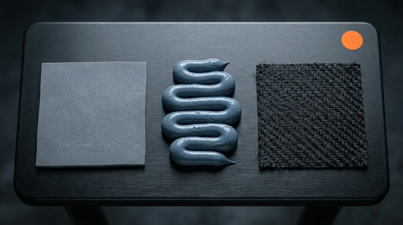
Format first, conductivity second: the same three materials differ far more in how they fill a gap than in their datasheet numbers.
From Thermal Budget to W/mK
Here is the step most 5G thermal management projects skip. You do not need to guess a conductivity class; you can calculate the one your joint allows, and the answer is often lower than expected — which frees you to optimise for thickness, pressure or contamination instead.
Start from the allowed temperature rise. Take the heat the joint must carry (Q), the area available (A), and the temperature difference you can afford across the interface (ΔT). The required resistance is ΔT / Q, and the interface material's resistance is its thickness divided by conductivity and area:
R = BLT / (k × A) — thickness in metres, area in square metres, conductivity in W/mK, resistance in °C/W. In practical units: R = 1000 × BLT(mm) / (k × A(mm²)).
Run it on a module-sized joint. A 12 W DSP transfers through 300 mm² of lid, and you decide the interface may cost 3 °C:
- A 1.5 mm pad at 3 W/mK: R = 1.67 °C/W, so ΔT = 20 °C. The joint fails on its own.
- The same pad thinned to 0.3 mm: R = 0.33 °C/W, ΔT = 4 °C.
- 0.3 mm at 6 W/mK: R = 0.17 °C/W, ΔT = 2 °C.
Read those three lines again, because they carry the practical lesson: cutting thickness by five cut the temperature rise by five, while doubling conductivity only halved it. Thickness, pressure and surface conformity are the strong levers; the W/mK column is the weak one. That is also why thermal impedance at a stated pressure and bond line is a better comparison between two materials than conductivity alone — the difference between the two metrics is worth understanding before you read another datasheet, and our explainer on thermal resistance versus thermal impedance draws the distinction with the same arithmetic.
A base station joint is more forgiving. Move 10 W through 600 mm² with a 0.5 mm pad at 3 W/mK and the rise is 2.8 °C; at 6 W/mK it is 1.4 °C. Work backwards for a 2 °C target and the requirement is about 4.2 W/mK — comfortably inside a mainstream pad family. The radio does not need an exotic material at that interface; it needs a pad that still touches both surfaces after ten years of thermal cycling and does not need 50% compression to conform.
Hardness is the second half of that sentence. A pad measuring 60–85 Shore OO needs real pressure to close a gap, which is fine under a bolted heat sink and impossible under a cage spring. A softer pad conforms at low force but compresses further, so the final thickness — and therefore the resistance — depends on the hardware, not on the datasheet. Specify the compression ratio, the resulting bond line, and the expected permanent deformation after cycling, or you have not specified the interface at all.

Dispensable materials hold a predictable bond line on uneven stacks — one reason automated radio assembly moved away from cut pads in high-count arrays.
What the Outdoor Enclosure Adds
Everything above assumed a clean bench. A pole-mounted radio adds four constraints that eliminate materials quietly, usually during qualification rather than before it.
Temperature swing. A radio on a mast can sit at −40 °C in winter and above 80 °C internally in summer sun. Materials in the −40 to 200 °C class cover that range, but cycling is the test that matters: pads lose contact if the compression set is high, and gels can separate from a surface that flexes at a different rate.
Water and weather. Sealing is a separate function from conduction. A silicone foam gasket rated UL 94 V-0 and IP68 keeps water out and does almost nothing for heat, while the conductive interface inside the sealed volume must be chosen to survive humidity without corrosion on the metal faces it touches. Coastal and offshore sites raise that bar again: salt-spray exposure is a routine part of outdoor telecom qualification, and it attacks the metal faces on either side of the joint rather than the conductivity of the material between them.
Vibration and handling. Mounting hardware on a mast is never static, and installation crews are not gentle. Pads that need adhesive to stay in place during assembly — or die-cut parts with tight tolerances that survive pick-and-place — reduce field failures more than a conductivity upgrade does. Choose shapes that assemble the same way every time; die-cut geometry is a thermal decision when the alternative is a mis-placed pad.
Flammability and safety. Enclosure materials and internal plastics in ICT equipment are held to flammability ratings, and a UL 94 V-0 grade is a routine requirement for pads, gaskets and potting compounds in radio and power hardware. The difference between material-level ratings — V-0 for solids, VTM-0 for thin films — matters when your interface is a 0.1 mm film rather than a 2 mm pad, as our comparison of UL 94 V-0 and VTM-0 explains. For the underlying test definition, UL publishes the combustion and fire test programmes for plastics that the ratings come from, and the safety standard behind most of these requirements for audio/video and ICT equipment is IEC 62368-1.
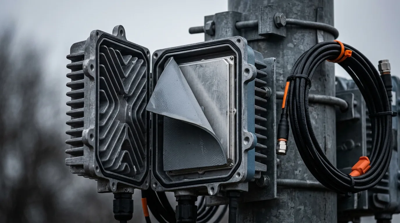
Outdoor radios are sealed, convection-cooled and cycled hard. Qualification failures here are usually mechanical, not thermal-conductivity failures.
Optical-Module-Specific Constraints
The transceiver side deserves its own checklist because its constraints are chemical and mechanical rather than simply thermal.
Outgassing. In a sealed cavity, volatile compounds that leave the pad can condense on optical surfaces — the classic fogging failure. Low-volatile silicone grades address it directly: ZIITEK's TIF®100L pad family holds its low-molecular siloxane content at minimal release across a 1.5–6.0 W/mK range. The test logic behind that requirement is standardised outside the materials industry: ASTM E595 measures total mass loss and collected volatile condensable materials from outgassing in a vacuum environment, which is why suppliers of cavity-mounted hardware are asked for TML and CVCM figures.
Silicone-free options. Where even a low-volatile silicone is unacceptable — imaging hardware and some optical assemblies — a non-silicone pad in the 1.5–10 W/mK range such as the Z-Paster®100 series removes the chemistry question entirely, at the cost of a narrower working range (−45 to 125 °C) and slightly different compressibility.
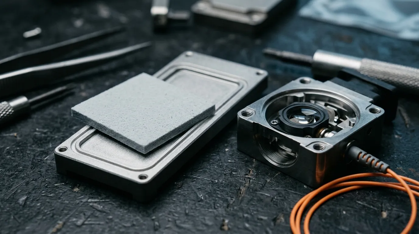
A non-silicone pad answers one question — what is in the cavity with the optics — before any conductivity comparison starts.
Thinness and low modulus. Module interfaces typically want a 0.2–0.5 mm pad or a thin phase-change sheet, and they want it to conform at the force a cage can apply. Where the stack is uneven and the gap is larger, a dispensable gap filler holds a 0.1–0.4 mm bond line without stressing the module — choosing between the two is the same analysis we applied to gap-filler selection for accelerator and server hardware.
Electrical behaviour near RF and high-speed traces. At millimetre-wave frequencies and at 50+ Gb/s per lane, a material's dielectric constant and loss tangent sit in series with signal integrity. A pad that fixes the temperature but shifts the impedance of a nearby trace has moved the problem, not solved it.
| Selection emphasis | Base station radio | Optical module |
|---|---|---|
| Primary metric | Interface impedance at the assembly's real pressure | Thinness and long-term contact stability |
| Format first choice | Preformed pad, or dispensable gel on uneven stacks | Thin pad or phase-change sheet |
| Hard constraint | Outdoor cycling, sealing, flammability | Low outgassing, low clamping force |
| Compliance to verify | UL 94 V-0, RoHS, REACH, potting for power stages | VTM-0 films, TML/CVCM data, RoHS, REACH |
| Rework | Pads are serviceable; cured gel usually is not | Hot-swap modules demand stable, non-migrating material |
A Four-Step Selection Order
The order matters more than the tools. Run it once on the worst hot spot in the design, not on the average — that is what makes 5G thermal management repeatable across a product family:
- Find the hot spot and its limit. Junction or case temperature, dissipated power at that component, and the temperature it must not exceed. One PA and one DSP, not the board's mean.
- Measure the gap and the force. Worst-case gap across the tolerance stack, the pressure the hardware actually applies, and whether the joint needs electrical isolation.
- Pick the format, then the grade. Use the table above to choose pad, gel, phase-change sheet, insulator or spreading sheet; only then compare grades inside that format at the same bond line and pressure.
- Verify against the environment and the paperwork. Thermal cycling and compression set for outdoor hardware; outgassing data for sealed optical cavities; UL 94 or VTM-0, RoHS and REACH for the market you ship into.
Five mistakes account for most of the failures we see:
- Choosing by W/mK alone. A 12 W/mK pad under a 1.5 mm bond line performs worse than a 6 W/mK pad at 0.3 mm.
- Ignoring the pressure. A hard pad on a low-force cage spring leaves an air gap that no datasheet predicts.
- Reusing one material across the whole unit. The radio's power supply, its PA interface and its sealing gasket are three different problems; potting compound or a foam gasket pressed into interface duty is a recurring error.
- Using a silicone pad inside a sealed optical cavity without outgassing data.
- Treating the thermal redesign as a purely thermal change. Structure, sealing and emissions all move together — 47 CFR Part 15 still governs what the enclosure may radiate after you change the metal and the gaps inside it.
What to Ask a Supplier Before You Qualify
Six questions separate a supplier who measured something from one who is quoting a number:
- What is the thermal impedance at my bond line and pressure? If the answer is only a W/mK figure, the datasheet cannot predict your result.
- What is the compression and permanent deformation after cycling? This decides whether the joint still touches in year five.
- What hardness, and how much force does it need to conform? Match it to your hardware, not to the sample kit.
- What is the outgassing data? TML and CVCM for sealed cavities; "silicone-free" alone is not a measurement.
- Which flammability ratings and environmental compliance apply, with documents? UL 94 V-0 or VTM-0 as applicable, RoHS and REACH — for the markets you sell into, not for a generic claim. The EU RoHS Directive and REACH are the two regimes most European customers will test first.
- Can you die-cut or dispense to my geometry, and what is the tolerance? A correct material placed imprecisely fails like a wrong one.
ZIITEK manufactures thermal pads, gap fillers, phase-change materials, graphite sheets, non-silicone pads and thermally conductive insulators for telecom and optical hardware, with IATF 16949, ISO 9001 and ISO 14001 systems, RoHS/REACH documentation and UL yellow card E331100 covering its pad and insulator grades. Starting points for a concrete answer: the thermal pad product range, the 5G and optical materials hub for the rest of this cluster, or our engineering team if you send the gap, the pressure and the temperature limit for the joint you are trying to close.